

Purification fan coil
A technology for purifying fans and coils, which is applied in mechanical equipment, space heating and ventilation, chemical instruments and methods, etc. It can solve problems such as uneven wind temperature and insufficient clean air, and achieve high purification efficiency, uniform temperature, The effect of high air purification efficiency
- Summary
- Abstract
- Description
- Claims
- Application Information
AI Technical Summary
Problems solved by technology
Method used
Image

Examples
Embodiment 1
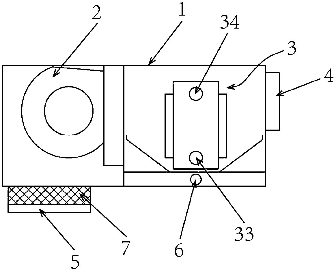
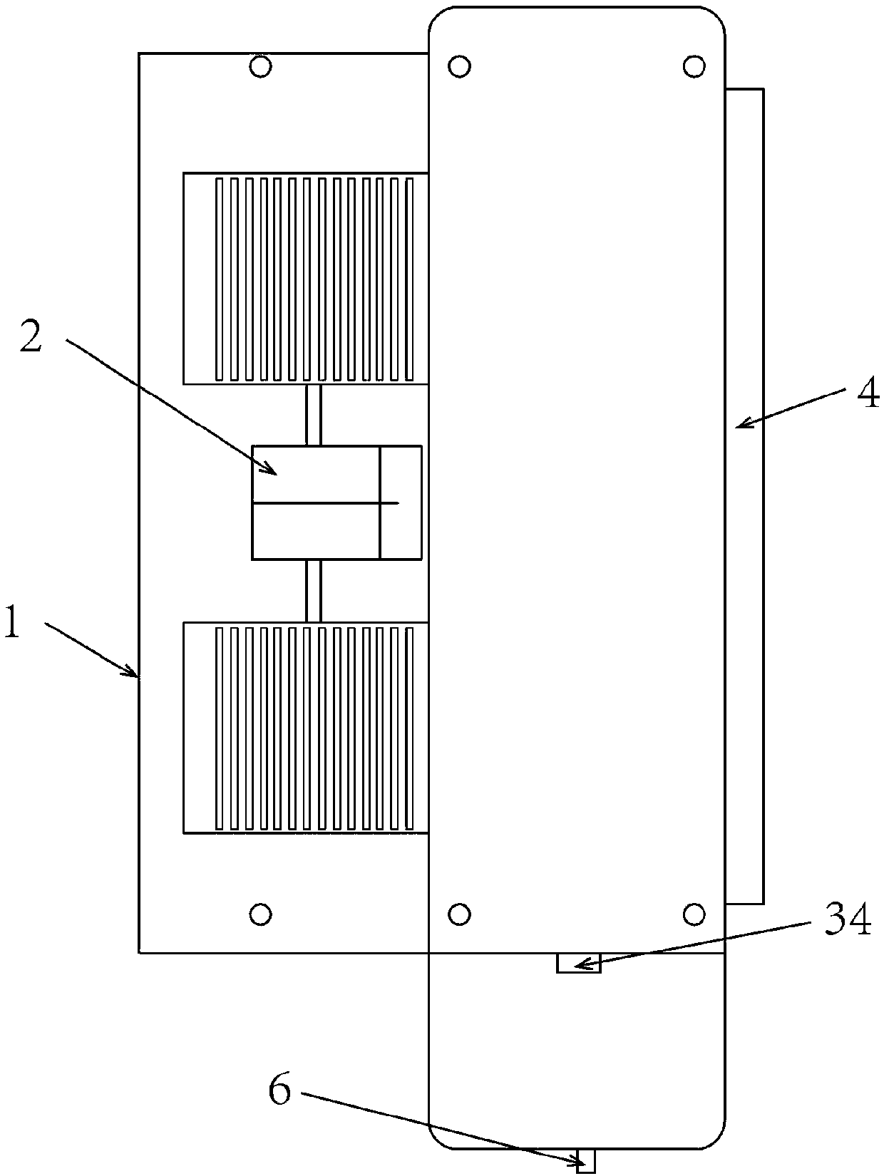
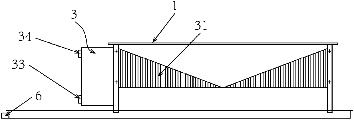
[0047] A purification fan coil unit, comprising a casing 1, a fan 2 and a surface cooler 3 both arranged in the casing 1, the casing 1 is provided with an air outlet 4, an air exchange port 5 and a condensed water outlet 6, and the surface cooler 3. Set between the fan 2 and the air outlet 4. The surface cooler 3 includes a heat dissipation sheet 31 and a coil 32 passing through the heat dissipation sheet 31. One end of the coil 32 is a water inlet 33, the other end is a water outlet 34, and there are 5 air exchange outlets. A filter screen matching the size of the air exchange port 5 is provided, a photocatalyst layer 8 is provided on the heat dissipation sheet 31, a temperature exchange area 9 is formed between the heat dissipation sheet 31 and the coil 32, and the temperature exchange area 9 is divided into at least two temperature exchange layers 91, the coiled pipe 32 is arranged in the temperature exchange layer 91, and the filter screen includes a filter screen frame and...
Embodiment 2
[0053] A purification fan coil unit, comprising a casing 1, a fan 2 and a surface cooler 3 both arranged in the casing 1, the casing 1 is provided with an air outlet 4, an air exchange port 5 and a condensed water outlet 6, and the surface cooler 3. Set between the fan 2 and the air outlet 4. The surface cooler 3 includes a heat dissipation sheet 31 and a coil 32 passing through the heat dissipation sheet 31. One end of the coil 32 is a water inlet 33, the other end is a water outlet 34, and there are 5 air exchange outlets. A filter screen matching the size of the air exchange port 5 is provided, a photocatalyst layer 8 is provided on the heat dissipation sheet 31, a temperature exchange area 9 is formed between the heat dissipation sheet 31 and the coil 32, and the temperature exchange area 9 is divided into at least two temperature exchange layers 91, the coiled pipe 32 is arranged in the temperature exchange layer 91, and the filter screen includes a filter screen frame and...
Embodiment 3
[0059] A purification fan coil unit, comprising a casing 1, a fan 2 and a surface cooler 3 both arranged in the casing 1, the casing 1 is provided with an air outlet 4, an air exchange port 5 and a condensed water outlet 6, and the surface cooler 3. Set between the fan 2 and the air outlet 4. The surface cooler 3 includes a heat dissipation sheet 31 and a coil 32 passing through the heat dissipation sheet 31. One end of the coil 32 is a water inlet 33, the other end is a water outlet 34, and there are 5 air exchange outlets. A filter screen matching the size of the air exchange port 5 is provided, a photocatalyst layer 8 is provided on the heat dissipation sheet 31, a temperature exchange area 9 is formed between the heat dissipation sheet 31 and the coil 32, and the temperature exchange area 9 is divided into at least two temperature exchange layers 91, the coiled pipe 32 is arranged in the temperature exchange layer 91, and the filter screen includes a filter screen frame and...
PUM
| Property | Measurement | Unit |
|---|---|---|
| particle diameter | aaaaa | aaaaa |
| particle diameter | aaaaa | aaaaa |
| particle diameter | aaaaa | aaaaa |
Abstract
Description
Claims
Application Information