heat sink

A technology of heat dissipation device and heat source, applied in indirect heat exchangers, lighting and heating equipment, etc., can solve the problems of limited heat dissipation effect of heat dissipation device, single cycle failure, poor flow effect, etc., to improve cycle efficiency and heat dissipation efficiency, avoid Thermal vaporization, reducing drying effect

Active Publication Date: 2019-06-14
ACER INC
View PDF7 Cites 0 Cited by
  • Summary
  • Abstract
  • Description
  • Claims
  • Application Information

AI Technical Summary

Problems solved by technology

However, if the temperature generated by the heat source is too high, the liquid working fluid boils into a gaseous state before returning to the accommodating tank, so that the single cycle fails, and the cooling device cannot effectively dissipate heat.
In addition, the working fluid flows in the closed circuit formed by the storage tank and the conduit only through its own phase change, the flow effect is poor and there may not be enough working fluid in the storage tank to react, so the cooling device The cooling effect of the limited

Method used


Image

  • heat sink
  • heat sink
  • heat sink

Examples


Embodiment Construction

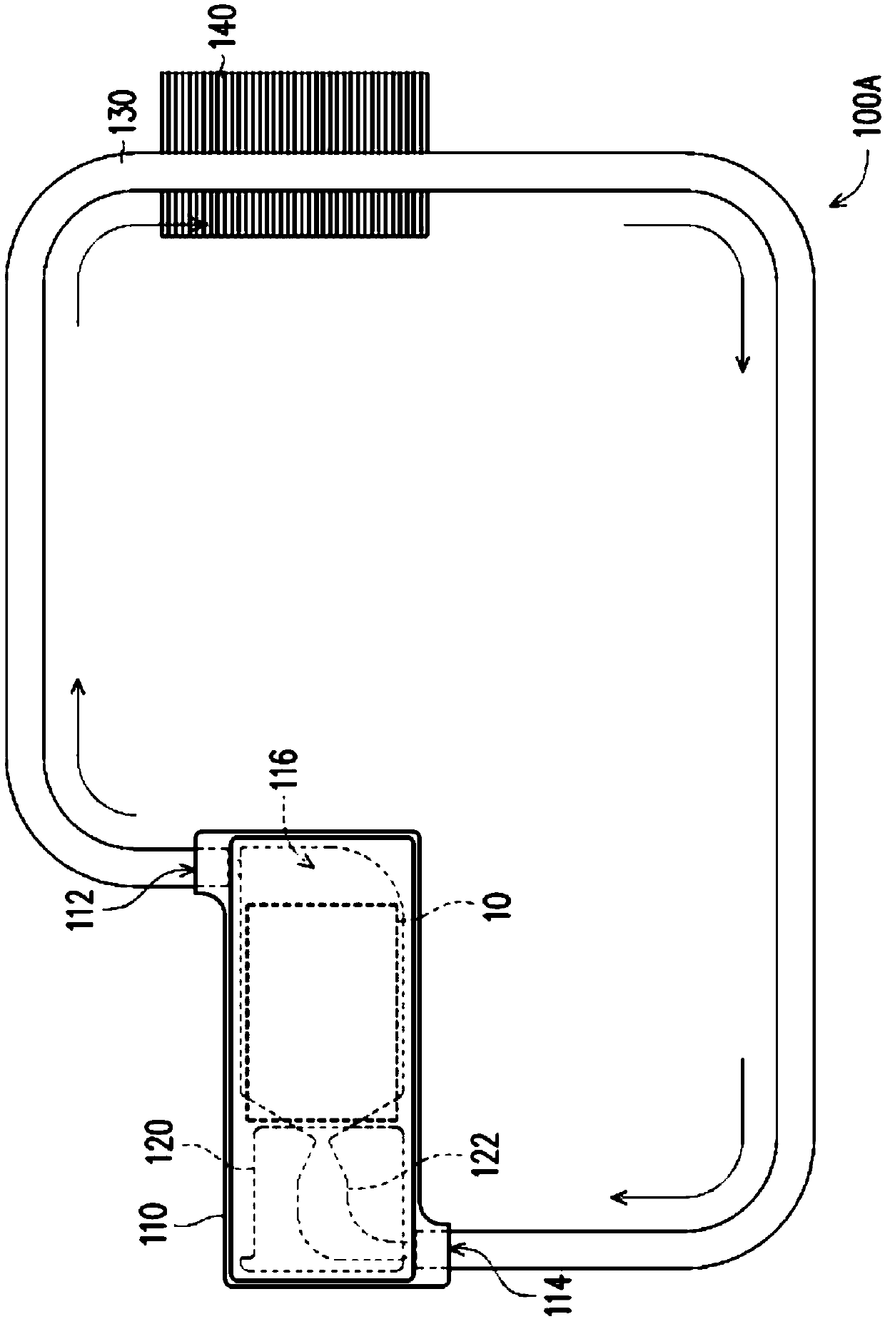
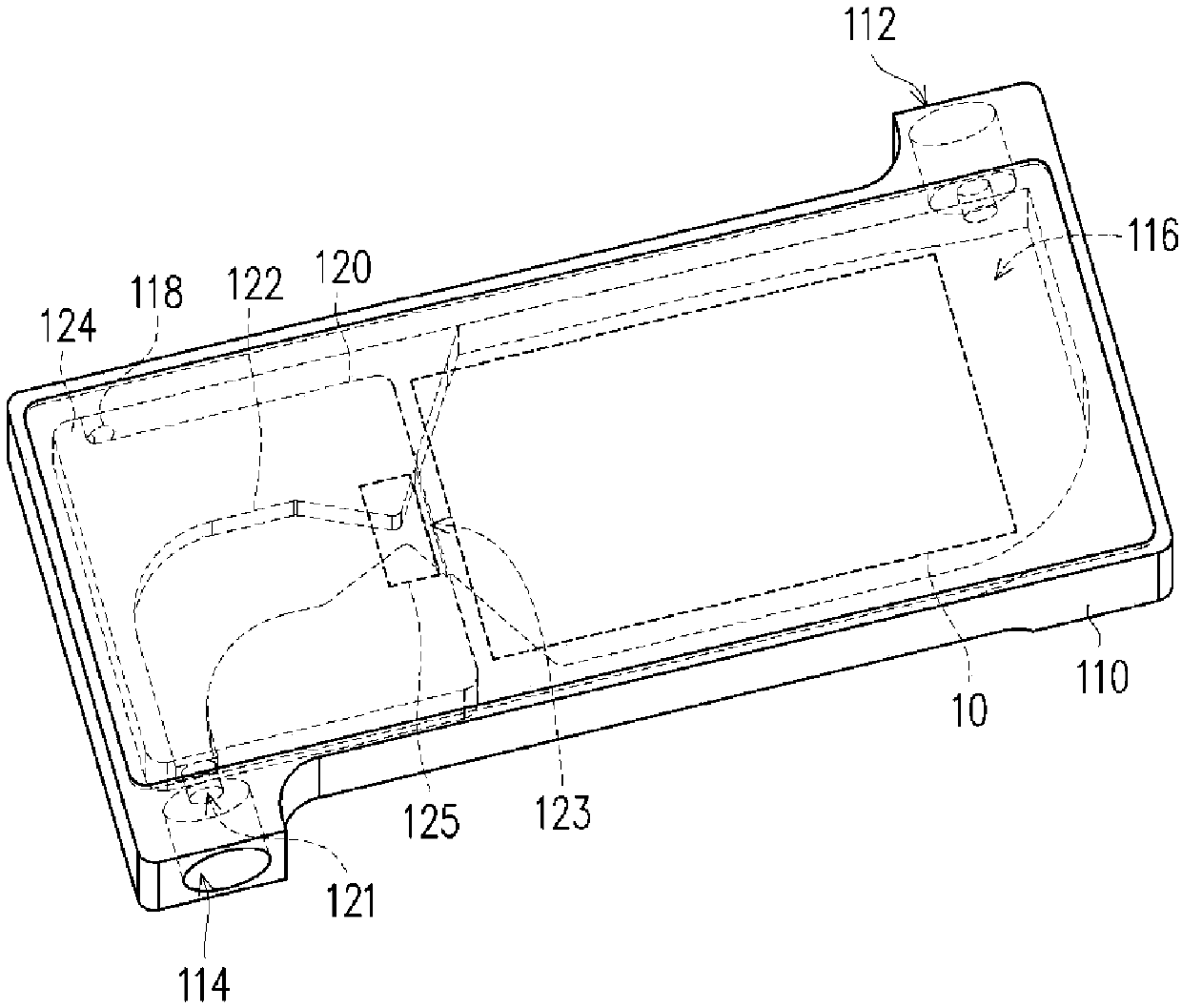
[0038] Figure 1A Shown is a schematic top view of a heat dissipation device according to an embodiment of the present invention. Figure 1B Shown as Figure 1A The three-dimensional schematic diagram of the accommodating slot of the heat dissipation device and the heat insulation unit. Please also refer to Figure 1A versus Figure 1B The heat sink 100A of this embodiment is suitable for dissipating heat from the heat source 10, where the heat source 10 is, for example, a heating element such as a chip or a processor in an electronic device, or a heat pipe, which can absorb heat from other heating elements and transfer heat to the device. Invented heat sink. In other words, the heat dissipation device 100A of this embodiment is suitable for electronic devices, such as portable electronic devices such as laptop computers, and the heat dissipation device 100A can be disposed in the housing of the electronic device, and the electronic device can be made by the thermal contact effect ...


PUM


Abstract

The invention relates to a heat-dissipating device and aims to dissipate heat from a heat source. The heat-dissipating device comprises an accommodating tank, a heat-insulating unit and a pipe body, wherein the accommodating tank comprises an outlet end, an inlet end and an accommodating space, and is used for receiving the heat from the heat source from above; the heat-insulating unit is arrangedin the accommodating space of the accommodating tank and comprises a heat-insulating nozzle; the heat-insulating nozzle comprises a first opening, a second opening and a necking part; the first opening communicates with the inlet end; the second opening communicates with the accommodating space; the necking part is adjacent to the second opening; and the pipe body is connected with the outlet endand the inlet end, and then a closed circulation loop is formed by the pipe body and the accommodating tank. By adoption of the heat-dissipating device provided by the invention, a working fluid canbe effectively protected against vaporization caused by the heat generated from the heat source before entering the accommodating tank, and the enough working fluid in the accommodating tank can be ensured. Consequently, the heat-dissipating device can have the relatively high heat-dissipating efficiency, and is applicable to a high-wattage electronic product.

Description

Technical field [0001] The present invention relates to a heat dissipation device, and more particularly to a heat dissipation device arranged in a portable electronic device. Background technique [0002] Generally, the single cycle of the heat sink is to place the heat source under the containing tank. After the liquid working fluid flows into the containing tank, it is heated by the heat source to boil into a gaseous state and flow out of the containing tank. The gaseous working fluid flows to the condenser. The cooling and condensing become liquid and return to the holding tank to complete a single cycle. However, if the temperature generated by the heat source is too high, the liquid working fluid will boil into a gaseous state before returning to the accommodating tank, which will cause the single cycle to fail and the heat sink will not be able to effectively dissipate heat. In addition, the working fluid flows in the closed circuit formed by the containing tank and the c...

Claims


Application Information

Patent Timeline
Patent Type & Authority Patents(China)
IPC IPC(8): F28D15/02
CPCF28D15/0266F28D15/0275
Inventor 郑丞佑廖文能谢铮玟柯召汉王勇智
Owner ACER INC
Why Eureka
Try Eureka