Eureka AIR delivers breakthrough ideas for toughest innovation challenges, trusted by R&D personnel around the world.

Optical fiber Fabry-Perot sensor welding and packaging device

A technology of Fab sensor and packaging device, which is applied in the direction of converting sensor output, using optical device to transmit sensing components, measuring devices, etc. It can solve the problems that the inner cavity of the hollow tube can not be welded with the inner cavity of the transmission fiber, etc., so as to improve the stress distribution. Effects of Uniformity, Improved Performance Stability, and Simplified Complexity

Active Publication Date: 2018-03-06
BEIJING CHANGCHENG INST OF METROLOGY & MEASUREMENT AVIATION IND CORP OF CHINA
View PDF10 Cites 2 Cited by
  • Summary
  • Abstract
  • Description
  • Claims
  • Application Information

AI Technical Summary

Problems solved by technology

[0005] The purpose of the present invention is to solve the problem that the existing welding cannot realize the internal fusion of the hollow tube cavity and the transmission optical fiber, and to provide a fiber optic sensor welding packaging device, which can improve the reliability of the welding point and reduce the sensor packaging technology. The influence of sensor performance, improving the stability of fiber optic FAP sensor in high temperature environment

Method used


Image

  • Optical fiber Fabry-Perot sensor welding and packaging device
  • Optical fiber Fabry-Perot sensor welding and packaging device
  • Optical fiber Fabry-Perot sensor welding and packaging device

Examples


Embodiment 1

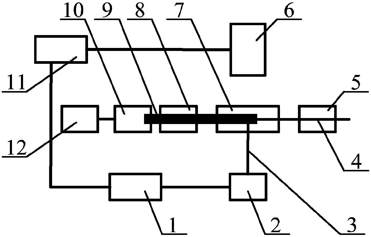
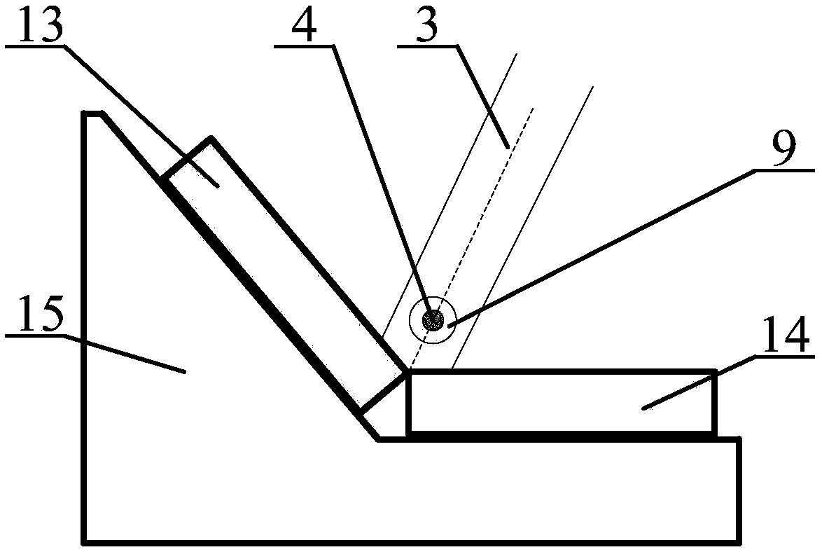
[0045] like figure 1 , Figure 4 and Figure 5 As shown, a method and device for welding and packaging an optical fiber Fab sensor, the steps of which are:

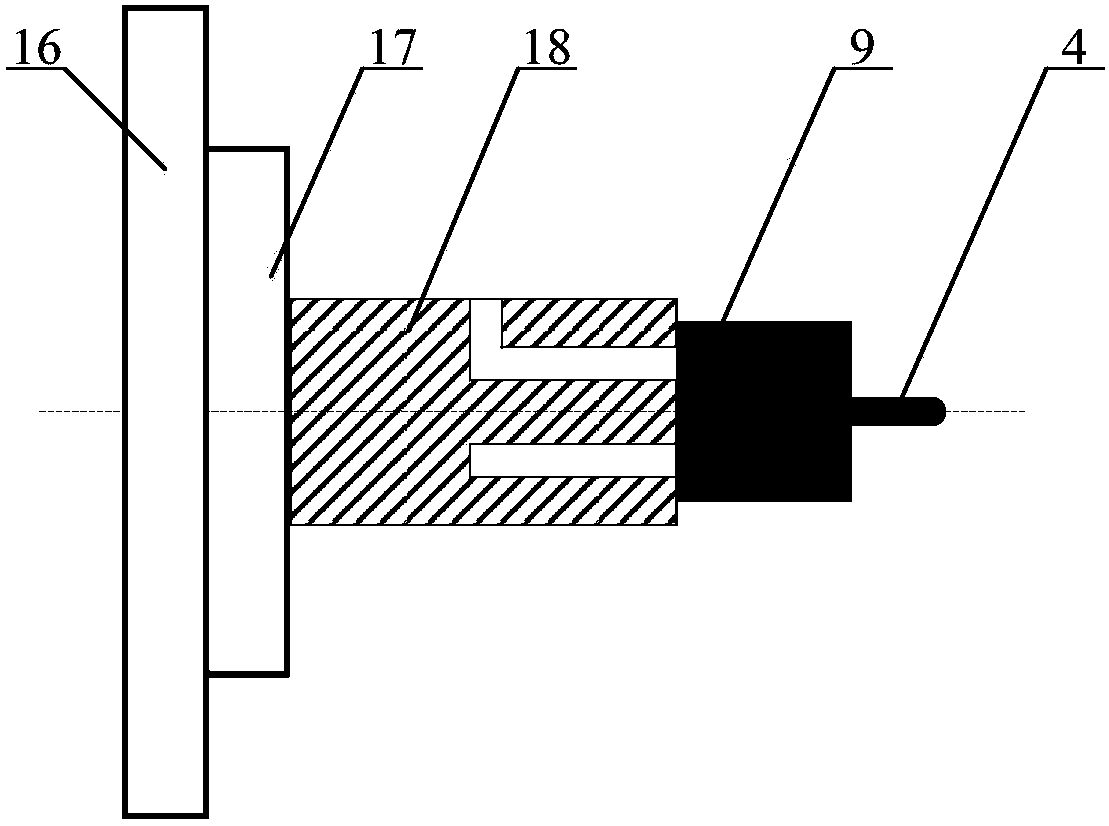
[0046] A single-mode silica fiber is used as the transmission fiber, a quartz hollow tube with an outer diameter of 2 mm and an inner diameter of 130 μm is used as a cylindrical hollow tube, and a manual rotating table is used as a rotating fixture. The transmission fiber holder 5 horizontally clamps the single-mode quartz optical fiber 19, and the hollow tube holder 8 horizontally clamps the quartz hollow tube 20; as image 3 As shown, the adsorption rotary device 10 is composed of an adsorption fixture 18, a rotary fixture 21 and an adsorption rotary bracket 16. The two fixtures are coaxially installed on the adsorption rotary bracket 16, and the end surface of the adsorption fixture 18 is in close contact with the end of the quartz hollow tube 20. can achieve reliable adsorption; figure 2 Shown, reflecting mirror ...

Embodiment 2

[0051] like Image 6 shown, based on Example 1 Figure 4 Schematic diagram of the device, the light source 24 is connected to the input end of the circulator 22, the output / return end of the circulator 22 is connected to the single-mode quartz fiber 19, and the output end of the circulator 22 is connected to the spectrometer 23. A spectrometer 23 is used to monitor the loss of transmitted light energy during the fusion splicing process to judge the splicing quality of the single-mode quartz optical fiber 19 and the quartz hollow tube 20 .

Embodiment 3

[0053] like Figure 7 As shown, the embodiment 1 Figure 5 The manual rotating table 21 in the present invention is replaced by an electric rotating table 25, and controlled by a computer 11, the ring-shaped welding packaging of the single-mode quartz optical fiber 19 and the quartz hollow tube 20 is automatically realized.


PUM


Abstract

The invention relates to an optical fiber Fabry-Perot sensor welding and packaging device, and belongs to the technical field of optical fiber sensor manufacturing. The device is characterized in thatan annular welding area is formed between an inner cavity of a cylindrical hollow tube and a transmission optical fiber, and welding is performed by using a rotating method. The optical fiber Fabry-Perot sensor welding and packaging device simplifies the complexity of a welding and packaging optical path structure, reduces the equipment cost, improves nonuniform stress distribution at a welding point and improves the welding and packaging reliability of the inner cavity of the cylindrical hollow tube and the transmission optical fiber and the performance stability of an optical fiber Fabry-Perot sensor in a high-temperature environment.

Description

technical field [0001] The invention relates to a welding and packaging device for an optical fiber F-P sensor, belonging to the technical field of optical fiber sensor manufacturing. Background technique [0002] Due to its small size, high temperature resistance, simple structure and flexible design, the optical fiber sensor has become the main technical means to solve the measurement of key parameters in high temperature environment. The fiber optic sensor generally includes three parts: a transmission fiber (micron-scale outer diameter), a cylindrical hollow tube (millimeter-scale outer diameter) and a sensitive structure. Straight and fixed, the other end of the cylindrical hollow tube is fixed with the sensitive structure, so as to realize the overall packaging of the optical fiber Fab sensor. The reliability of the packaging process directly affects the stability of the performance of the fiber optic sensor at high temperature. The current packaging technology (such ...

Claims


Application Information

Patent Timeline
IPC IPC(8): G01D5/26B23K26/21
CPCB23K26/21G01D5/268
Inventor 隋广慧江琴陈爽张慧君张欣颍
Owner BEIJING CHANGCHENG INST OF METROLOGY & MEASUREMENT AVIATION IND CORP OF CHINA
Why Eureka
Eureka Blog
Learn More