
3D printing precision monitoring device based on laser detection

A monitoring device and 3D printing technology, applied in the field of 3D printing, can solve the problems that the detection method cannot achieve high-precision detection, the difficulty and difficulty of precision detection, etc., so as to improve the precision of laser monitoring, improve the precision of monitoring, and improve the quality of detection. Effect

Pending Publication Date: 2018-03-06
ANXI XIANCAI TEA MACHINERY CO LTD
View PDF17 Cites 3 Cited by
  • Summary
  • Abstract
  • Description
  • Claims
  • Application Information

AI Technical Summary

Problems solved by technology

There are many influences on the accuracy of 3D printing, such as the influence of the above-mentioned injection head and temperature, and further integrating the above-mentioned technical solutions and the existing problems in reality, and combining the technical solutions that are currently widely used, the main defects that still exist are mainly reflected in the model. Establish the difference from the actual printing, and the detection device is very important in this process, and because in the printing process, the thickness of the layer is generally in the micron level, and the precision detection of this order of magnitude is very difficult, Since the detection of accuracy is relatively difficult, it is even more difficult to further require the accuracy to meet the existing printing accuracy requirements. At least in the current conventional detection methods, high-precision detection cannot be achieved.

Method used


Image

  • 3D printing precision monitoring device based on laser detection
  • 3D printing precision monitoring device based on laser detection
  • 3D printing precision monitoring device based on laser detection

Examples


Embodiment

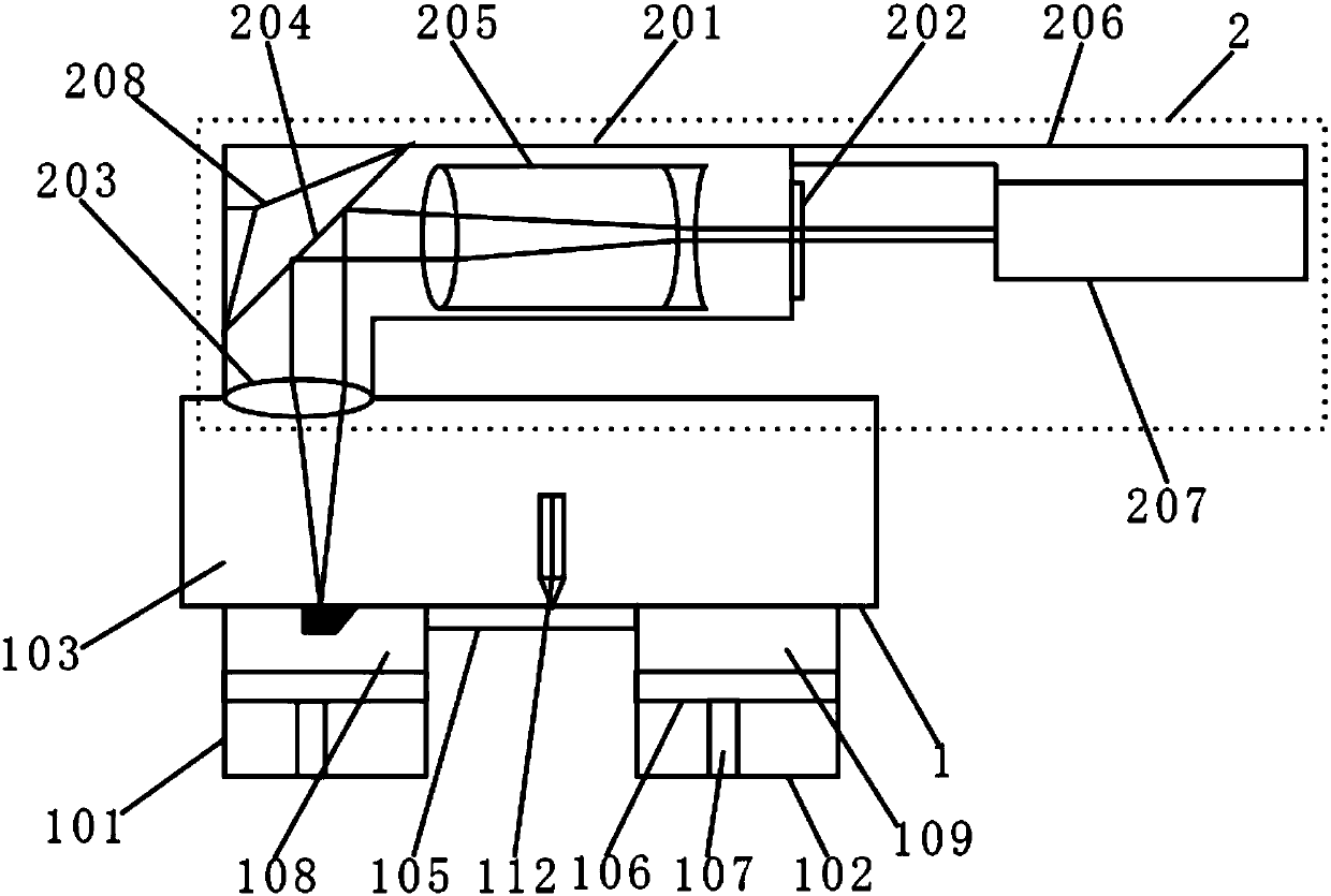
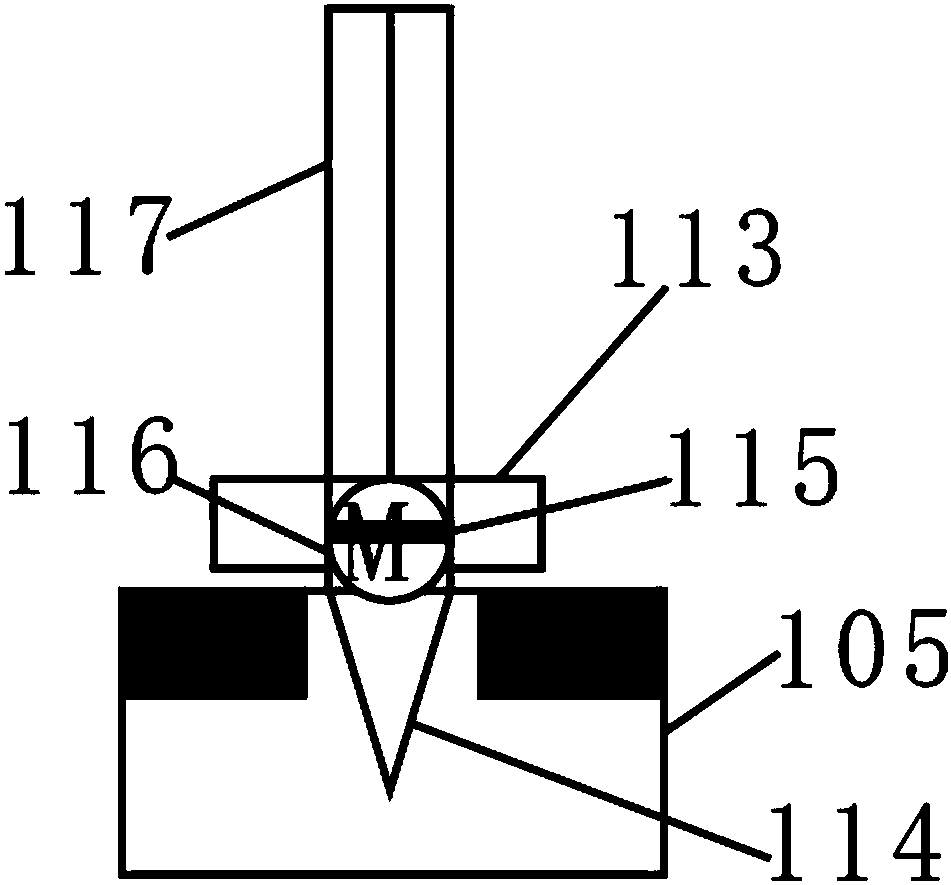
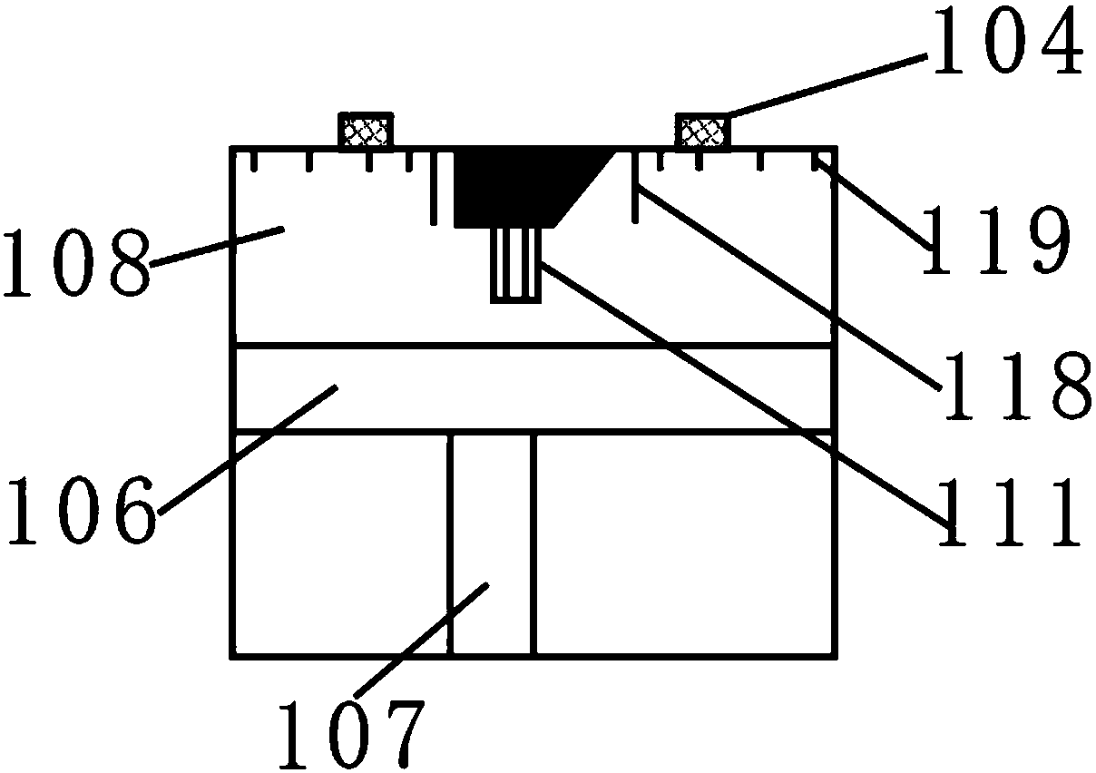
[0031] like Figure 1 to Figure 4 As shown, the present invention provides a 3D printing accuracy monitoring device based on laser detection, which includes a molding chamber 1 and a laser interference monitoring device. The bottom ends of the molding chamber 1 are respectively fixed with a molding cylinder 101 and a powder cylinder 102. The laser interference monitoring device 2 is arranged directly above the molding cylinder 101 , and the laser interference monitoring device 2 is fixedly installed on the top of the molding chamber 1 .

[0032]The molding chamber 1 includes an inner cavity 103, and the bottom of the inner cavity 103 is fixedly equipped with an injection head installation base 104 for installing a printing injection head. The number of the injection head installation bases 104 is three, three The injection head mounting bases 104 are evenly distributed with the center of the molding cylinder 101 as the symmetrical center, and a numerical control connection por...


PUM


Abstract

The present invention discloses a 3D printing precision monitoring device based on laser detection. The device comprises a prototyping room and a laser interference monitoring device. A prototyping cylinder and a powder cylinder are respectively fixedly installed at two ends of the bottom portion of the prototyping room; the laser interference monitoring device is arranged above the prototyping cylinder; and the laser interference monitoring device is fixedly installed at the top portion of the prototyping cylinder. The laser interference monitoring device is arranged and interference fringesare additionally arranged at the outer side of a fixed pedestal of a test piece and are distributed in strict accordance with a laser interference law, a coherent light source is formed after a generated laser beam is processed and is irradiated onto the test piece; and moreover, in a printing process, a workpiece is always located under the irradiation of the interference laser, any deviation error can be amplified by an interference phenomenon and then is displayed on the interference fringes, a tiny change is amplified by changing of the interference fringes, and therefore, nano-scale monitoring can be achieved, and the laser monitoring precision in the 3D printing process can be greatly improved.

Description

technical field [0001] The invention relates to the technical field of 3D printing, in particular to a 3D printing accuracy monitoring device based on laser detection. Background technique [0002] 3D printing is also known as three-dimensional printing. Its scientific name is additive manufacturing, which refers to a rapid manufacturing technology that fuses and aggregates materials at one time. It is based on digital model files and uses bondable materials such as powdered metal or plastic. By printing layer by layer and superimposing successive layers of different shapes to construct any three-dimensional object, 3D printing is essentially one of the rapid prototyping technologies. [0003] The most prominent advantage of 3D printing technology is that it does not require molds or machining, and can directly generate objects of any shape from the designed computer graphics data. 3D printing technology can process parts that are difficult to manufacture by traditional met...

Claims


Application Information

Patent Timeline
Patent Type & Authority Applications(China)
IPC IPC(8): G01M11/08B29C64/30B33Y40/00
CPCG01M11/083B33Y40/00Y02P10/25
Inventor 胡运平
Owner ANXI XIANCAI TEA MACHINERY CO LTD
Learn More