Light source device, image projection device, installation method of light source device

A light source device and image projection technology, which is applied to the cooling/heating device of the lighting device, the components of the lighting device, and the light source, etc., can solve the problems of enlargement and increased noise of the air supply mechanism of the frame of the image projection device, and achieve The effects of suppressing the increase in noise of the blower mechanism, stabilizing the light output, and suppressing the enlargement of the housing

Active Publication Date: 2020-12-01
RICOH KK
View PDF13 Cites 0 Cited by
  • Summary
  • Abstract
  • Description
  • Claims
  • Application Information

AI Technical Summary

Problems solved by technology

[0012] However, enlarging the radiating area of ​​a heat radiating part arranged on the downstream side in this way, or making the cooling fan rotate at a high speed in accordance with the heat dissipated by the radiating part may cause enlargement of the frame of the image projection device and noise of the air blowing mechanism. growing problem

Method used


Image

  • Light source device, image projection device, installation method of light source device
  • Light source device, image projection device, installation method of light source device
  • Light source device, image projection device, installation method of light source device

Examples


Embodiment 1

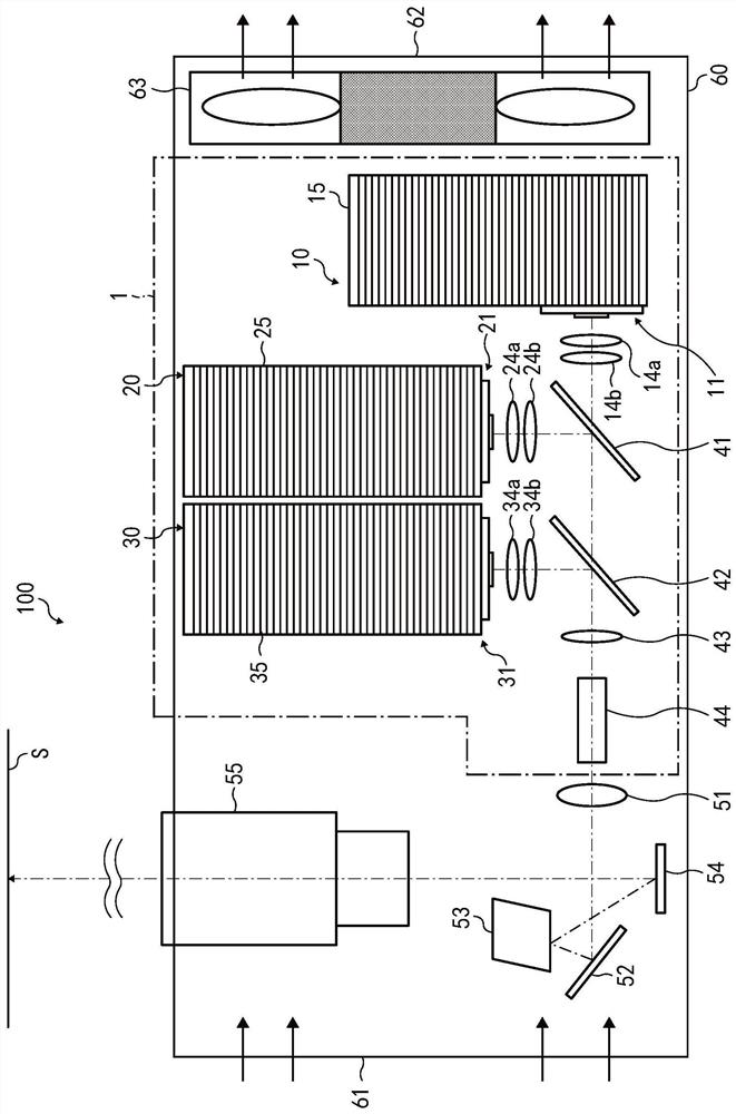
[0043] First, Example 1 of projector 100 of this embodiment will be described with reference to the drawings.

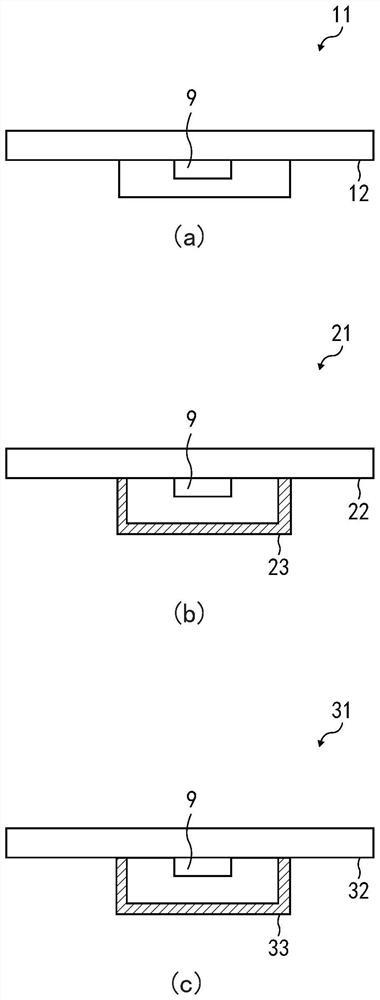
[0044] figure 1 is a schematic diagram of the projector 100 of this embodiment. figure 2 is a schematic diagram of a light source provided in each light source section, wherein, figure 2 Among them, (a) is a schematic view of the internal structure of the blue light source 11 provided in the blue light source part 10, (b) is a schematic view of the internal structure of the red light source 21 provided in the red light source part 20, and (c) is a schematic view of the internal structure of the red light source 21 provided in the red light source part 20. A schematic diagram of the internal structure of the green light source 31 of the unit 30.

[0045] In each of the above-mentioned figures, the same components are given the same reference numerals, and repeated descriptions are omitted.

[0046] Such as figure 1 As shown, the projector 100 has a frame body 60...

Embodiment 2

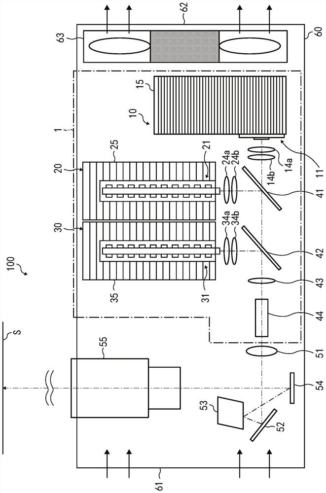
[0121] Hereinafter, Example 2 of projector 100 of this embodiment will be described using the drawings.

[0122] image 3 is a schematic diagram showing the projector 100 according to this embodiment. Figure 4It is a schematic view showing the internal structure of the light source of the light source unit using a rod-shaped uniform light lens, wherein (a) shows the internal structure of the red light source 21 of the red light source unit 20, and (b) shows the inside of the green light source 31 of the green light source unit 30. constitute.

[0123] Compared with the projector 100 of the above-mentioned embodiment 1, the projector 100 of the present embodiment is only different from the configuration of the light sources of the two light source parts among the three light source parts of the light source device 1. The configuration of the red light source 21 of the red light source unit 20 and the green light source 31 of the green light source unit 30 .

[0124] Therefo...

Embodiment 3

[0142] Hereinafter, Example 3 of projector 100 of this embodiment will be described using the drawings.

[0143] Figure 5 is a schematic diagram showing the projector 100 according to this embodiment.

[0144] Compared with the projectors of the first and second embodiments, the projection 100 of this embodiment is only different from the arrangement of the light source and the heat dissipation part of each light source part of the light source device 1. Specifically, the projection 100 of this embodiment In the light source device 1 included in the projector 100 , the light source of each light source unit is separated from the heat sink, and heat is transferred between the light source of each light source unit and the heat sink through a heat transfer device, that is, a heat pipe.


PUM


Abstract

The present invention relates to a light source device, an image projection device, and an installation method of the light source device. An object of the present invention is to provide an image projection device that not only makes the lifespan of the light-emitting elements in the light sources of each light source unit substantially the same, but also stabilizes the light output of each light source unit and inhibits the A light source device with an enlarged frame and increased noise from the air blower. The light source device (1) is configured such that the blue light source portion (10), the red light source portion (20), and the green light source portion (30) that emit light in different wavelength bands have blue light source elements (9) of the same type that have substantially the same lifespan. When isochronous, the heat dissipation portion of each light source portion is provided as follows. That is, when the calorific value of the light source in each light source unit is set to Q, and the set temperature that the light-emitting element in the light source of each light source unit must not exceed in order to obtain the predetermined light intensity and life is set to T, according to the In order of increasing T / Q value, the heat dissipation parts of each light source part are arranged in order from the upstream to the downstream of the cooling air duct.

Description

technical field [0001] The present invention relates to a light source device, an image projection device, and a method for setting the light source device. Background technique [0002] In a conventional image projection device equipped with a blower device, the heat dissipation members of the first light source unit, the second light source unit, and the third light source unit that emit light of different wavelength bands in the light source device are provided between the air inlet and the exhaust port. on the cooling duct between the air ports. [0003] For example, Patent Document 1 describes an image projection device (image display device) including the following light source device provided with a plurality of light source units using light emitting elements (semiconductor lasers) in a casing. [0004] Among the first light source (blue laser light source device), the second light source part (red laser light source device), and the third light source (green laser ...

Claims


Application Information

Patent Timeline
Patent Type & Authority Patents(China)
IPC IPC(8): G03B21/16G03B21/20
CPCG03B21/16G03B21/204G03B33/06G03B21/2013F21V29/51F21V29/67F21V29/70F21V29/713F21Y2115/30F21Y2113/13F21K9/64F21V9/30
Inventor 西森丈裕藤冈哲弥御沓泰成金井秀雄土屋聪真下淳
Owner RICOH KK
Why Eureka
Try Eureka