
Motor controller busbar capacitor charge-discharge circuit

A charge-discharge circuit and motor controller technology, which is applied to battery circuit devices, current collectors, circuit devices, etc., can solve the problems of slow passive discharge and discharge speed, inconsistent control coordination, and burnt pre-charge relays, etc., to achieve faster discharge speed, The effect of safe and effective charging

Inactive Publication Date: 2018-03-06
安徽一维新能源技术有限公司
View PDF4 Cites 4 Cited by
  • Summary
  • Abstract
  • Description
  • Claims
  • Application Information

AI Technical Summary

Problems solved by technology

[0002] There are two main ways to realize the charging and discharging of the bus capacitor of the existing motor controller. One is to use the thermistor inside the controller to increase the power resistance of the pre-charging method. The thermistor is mainly a PTC thermistor. Due to the positive temperature coefficient characteristics of PTC, there will be cases where the power cannot be charged, resulting in the failure of the pre-charging circuit
The discharge is mainly realized by a high-power resistor connected in parallel to the bus capacitor, and the discharge resistor is often hung on the DC bus capacitor to generate power loss
[0003] The other is that there is an auxiliary pre-charging circuit outside the controller. The VCU or BMS of the vehicle controls the pre-charging relay to pre-charge the bus capacitor of the controller. The controller does not perform any operation. The heat accumulation in the pre-charging resistance and the load cut-off of the relay will result in damage to the pre-charging resistance or burning of the pre-charging relay
The above two methods have disadvantages, especially when the controller bus capacitor is connected in parallel with a high-power resistor, the passive discharge speed is slow, and unnecessary power loss will be generated.

Method used


Image

  • Motor controller busbar capacitor charge-discharge circuit
  • Motor controller busbar capacitor charge-discharge circuit
  • Motor controller busbar capacitor charge-discharge circuit

Examples


Embodiment Construction

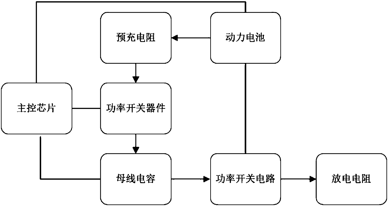
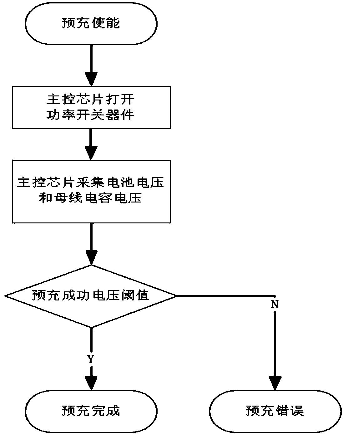
[0022] Such as figure 1 As shown, a motor controller bus capacitor charging and discharging circuit includes a power battery, a pre-charging resistor, a power switching device, a main control chip, a bus capacitor, a power switching circuit, and a discharging resistor;

[0023] The power battery is electrically connected to the pre-charging resistor, the pre-charging resistor is electrically connected to the power switch device, the power switch device is electrically connected to the bus capacitor, and the bus capacitor is connected to the power switch circuit Electrically connected, the power switch circuit is electrically connected to the discharge resistor;

[0024] The main control chip is in control connection with the power battery, the power switch device and the bus capacitor, and the power battery is electrically connected with the power switch circuit.

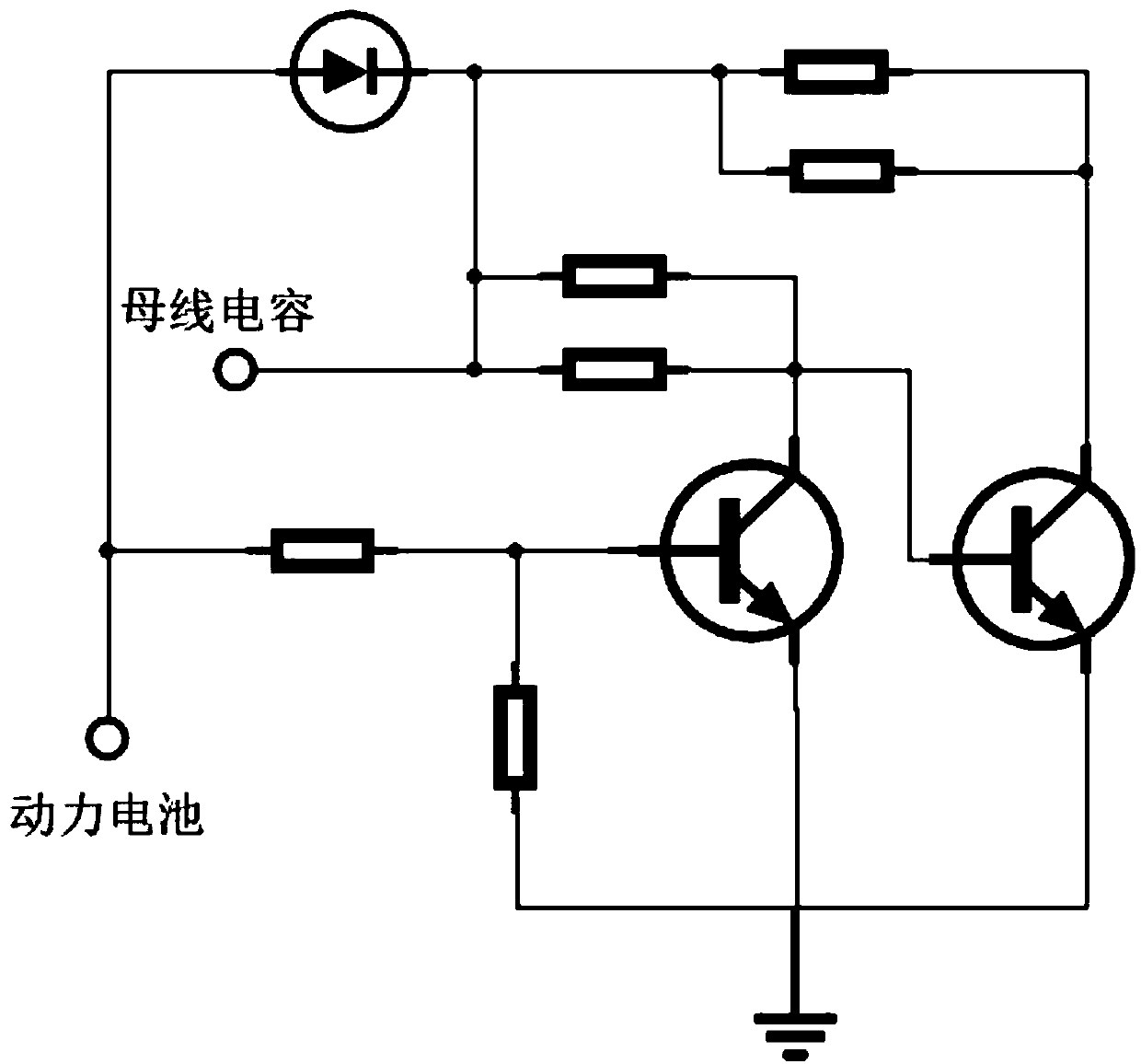
[0025] Wherein, the pre-charging resistance is composed of two or three resistances connected in parallel.

[0...


PUM


Abstract

The invention discloses a motor controller busbar capacitor charge-discharge circuit which comprises a power battery, a pre-charge resistor, a power switching device, a main control chip, a busbar capacitor, a power switching circuit and a discharge resistor; the power battery is electrically connected with the pre-charge resistor, the pre-charge resistor is electrically connected with the power switching device, the power switching device is electrically connected with the busbar capacitor, the busbar capacitor is electrically connected with the power switching circuit, and the power switching circuit is electrically connected with the discharge resistor; the main control chip is in control connection with the power battery, the power switching device and the busbar capacitor, and the power battery is electrically connected with the power switching circuit. The problem that pre-charge inside the controller is invalid is solved by the aid of the motor controller busbar capacitor charge-discharge circuit, safer and more effective busbar capacitor charge-discharge can be realized, busbar normally-hanged parallel connection high-power discharge resistance can be removed by the aid ofthe design of the discharge circuit, and the discharge speed is accelerated.

Description

technical field [0001] The invention belongs to the field of discharge circuits, and relates to a motor controller, in particular to a motor controller bus capacitor charging and discharging circuit. Background technique [0002] There are two main ways to realize the charging and discharging of the bus capacitor of the existing motor controller. One is to use the thermistor inside the controller to increase the power resistance of the pre-charging method. The thermistor is mainly a PTC thermistor. Due to the positive temperature coefficient characteristic of PTC, there may be cases where the battery cannot be charged, resulting in the failure of the pre-charging circuit. The discharge is mainly achieved by a high-power resistor connected in parallel to the bus capacitor, and the discharge resistor is often hung on the DC bus capacitor to generate power loss. [0003] The other is that there is an auxiliary pre-charging circuit outside the controller. The VCU or BMS of the ...

Claims


Application Information

Patent Timeline
Patent Type & Authority Applications(China)
IPC IPC(8): H02J7/34
CPCH02J7/345Y02E60/10
Inventor 吴升朱立山吕东冬翟周林汪国军黄少峰
Owner 安徽一维新能源技术有限公司
Learn More