High-efficient tea tree essential oil distillation pot

A technology of tea tree essential oil and distillation tank, which is applied in the directions of essential oil/spices, fat production, solid solvent extraction, etc. It can solve the problems of low distillation efficiency and insufficient distillation of tea tree leaves, etc., and achieve the effect of improving distillation efficiency and work efficiency

Inactive Publication Date: 2018-03-09
成都元始信息科技有限公司
View PDF0 Cites 1 Cited by
  • Summary
  • Abstract
  • Description
  • Claims
  • Application Information

AI Technical Summary

Problems solved by technology

[0003] The purpose of the present invention is: in order to solve the problem of insufficient distillation of tea tree leaves and low distillation efficiency in the existing tea tree essential oil distillation tank, the present invention provides a high-efficiency tea tree essential oil distillation tank, which can turn the tea tree leaves during the distillation process. Stir so that the tea leaves are heated evenly and fully distilled

Method used


Image

  • High-efficient tea tree essential oil distillation pot
  • High-efficient tea tree essential oil distillation pot
  • High-efficient tea tree essential oil distillation pot

Examples


Embodiment 1

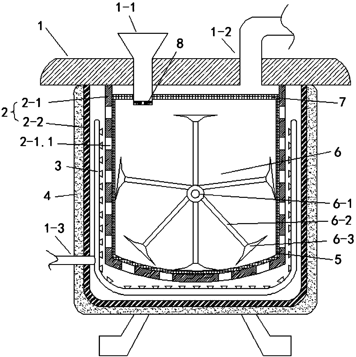
[0022] Such as figure 1 and figure 2 As shown, the present embodiment provides a high-efficiency tea tree essential oil distillation tank, comprising a distillation tank body 2 and a tank cover 1 matched with the distillation tank body 2, and the tank cover 1 is respectively provided with an exhaust port 1-2 and an anti-clogging tank. The feed hopper 1-1 of the component 8 is provided with a steam inlet 1-3 on the distillation tank body 2, and the distillation tank body 2 includes an inner tank 2-1 and an outer shell 2-2, and the outer wall of the inner tank 2-1 and the outer shell The inner wall of 2-2 constitutes a heating cavity, and the outer wall of the shell 2-2 is provided with a thermal insulation layer 4, and the thermal insulation layer 4 is filled with glass fibers, and the inner tank 2-1 is surrounded by the heating cavity. A U-shaped heating pipe 3 connected to the steam inlet 1-3 is provided, a distillation cavity is formed inside the inner tank 2-1, and the di...

Embodiment 2

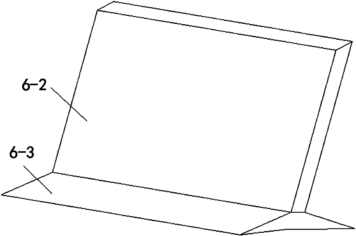
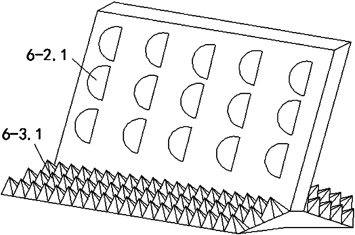
[0024] Such as image 3 and Figure 4 As shown, this embodiment is further optimized on the basis of Embodiment 1, specifically: the anti-clogging assembly 8 includes two rotating shafts 8 that are arranged at the inner bottom of the feed hopper 1-1 and are located at the same height and turn in opposite directions -1, each rotating shaft 8-1 is staggered with a number of inclined protruding rods 8-1.1, and the two rotating shafts 8-1 are driven by two motors that turn in opposite directions, which can guide the tea leaves and prevent the tea leaves Block the outlet of the feed hopper 1-1, a number of pulverizing pieces 6-2.1 are evenly arranged on the stirring plate 6-2, and a number of pulverizing teeth 6-3.1 are arranged on the inclined surface of the stirring block 6-3, and the pulverizing pieces are passed through 6-2.1 and crushing teeth 6-3.1 Preliminarily crushing the tea tree leaves during the stirring process can make the tea tree leaves more fully contact with the ...


PUM


Abstract

The invention discloses a high-efficiency tea tree essential oil distillation tank, which relates to the technical field of essential oil production and processing equipment. The invention includes a distillation tank body and a tank cover matched with the distillation tank body. The tank cover is respectively provided with an exhaust port and an anti-clogging device. The feed hopper of the assembly is provided with a steam inlet on the distillation tank body. The distillation tank body includes an inner tank and an outer shell. U-shaped heating tube, the inner tank forms a distillation chamber, the distillation chamber is connected to the exhaust port, the inner tank is provided with a through hole connecting the heating cavity and the distillation chamber, and the distillation chamber is provided with a turning device for stirring the tea leaves. Stirring component, the invention stirs the tea tree leaves during the distillation process, so that the tea tree leaves are heated evenly, fully distilled, and the distillation efficiency is improved.

Description

technical field [0001] The invention relates to the technical field of essential oil production and processing equipment, and more specifically relates to a high-efficiency tea tree essential oil distillation tank. Background technique [0002] Tea tree essential oil is the extract of tea tree, which has the functions of sterilizing and anti-inflammatory, shrinking pores, treating colds and improving dysmenorrhea, etc. Tea tree essential oil is mainly extracted from tea tree leaves, and is extracted by steam distillation, but currently the tea tree leaves are steamed During distillation, the tea leaves are generally stacked in batches in the distillation tank for distillation. During the distillation process, there is a phenomenon of insufficient distillation, resulting in a waste of resources. The existing distillation tanks also have tea leaves layered for distillation. , although the phenomenon of insufficient distillation has been improved to a certain extent, the distil...

Claims


Application Information

Patent Timeline
Patent Type & Authority Applications(China)
IPC IPC(8): C11B9/02B01D11/02
CPCC11B9/027B01D11/0257B01D2011/007
Inventor 赵元兵
Owner 成都元始信息科技有限公司
Why Eureka
Try Eureka