Connecting piece, assembling component and assembling method

An assembly method and technology for connecting parts, which are applied in the direction of connecting components, thin plate connections, mechanical equipment, etc., can solve the problems of insufficient standardization of precision, easy loosening of time, and difficult processing, and achieve variability and diversity, good protection. Rounded edge processing, the effect of reducing production costs

Pending Publication Date: 2018-03-09
孙绍顺
View PDF0 Cites 4 Cited by
  • Summary
  • Abstract
  • Description
  • Claims
  • Application Information

AI Technical Summary

Problems solved by technology

However, there are certain defects in the existing connection methods. For example, if a pure wood mortise and tenon structure is used for handover between plates, the processing is difficult, the technical requirements for carpenters are high, the cost is high, and the wood used for mortise and tenon joints is wasted. Its precision is not good, and the control standardization is not strong enough; if metal parts are used to anchor the plates, it will be easy to loosen after a long time, and it is difficult to disassemble and assemble the product twice. The product assembly is difficult, and the variability is not strong enough. Assembling and extending settings, it is difficult to cope with the changes in the working form and combination size required by modular furniture

Method used


Image

  • Connecting piece, assembling component and assembling method
  • Connecting piece, assembling component and assembling method
  • Connecting piece, assembling component and assembling method

Examples


Embodiment 1

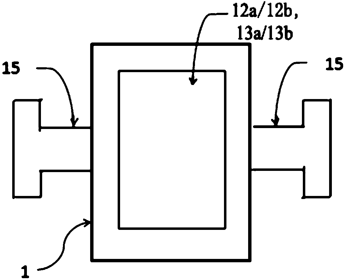
[0063] The connector 1 in this embodiment includes a first chuck 13a and / or a second chuck 13b, a first slot 12a and / or a second slot 12b, and a snap-in portion 15; the first end of the connector 1 There is a first card head 13a and / or a first card slot 12a, and the second end of the connector 1 has a second card slot 12b and / or a second card head 13b, the shape of the card slot is set to match the card head, so that the connectors 1 can be detachably plugged in through the cooperation of the chuck head and the slot; At the end, the clamping part 15 is set to match the groove 3 on the connected part 2 so that the clamping part 15 can be detachably clamped and fixed with the connected part 2 . image 3 A schematic cross-sectional view of the connecting piece 1 is shown. It should be understood that the shape and number of the snap-in portion 15 are not limited to the situation shown in the figure, as long as the shape of the snap-in portion 15 can match with the groove 3 on th...

Embodiment 2

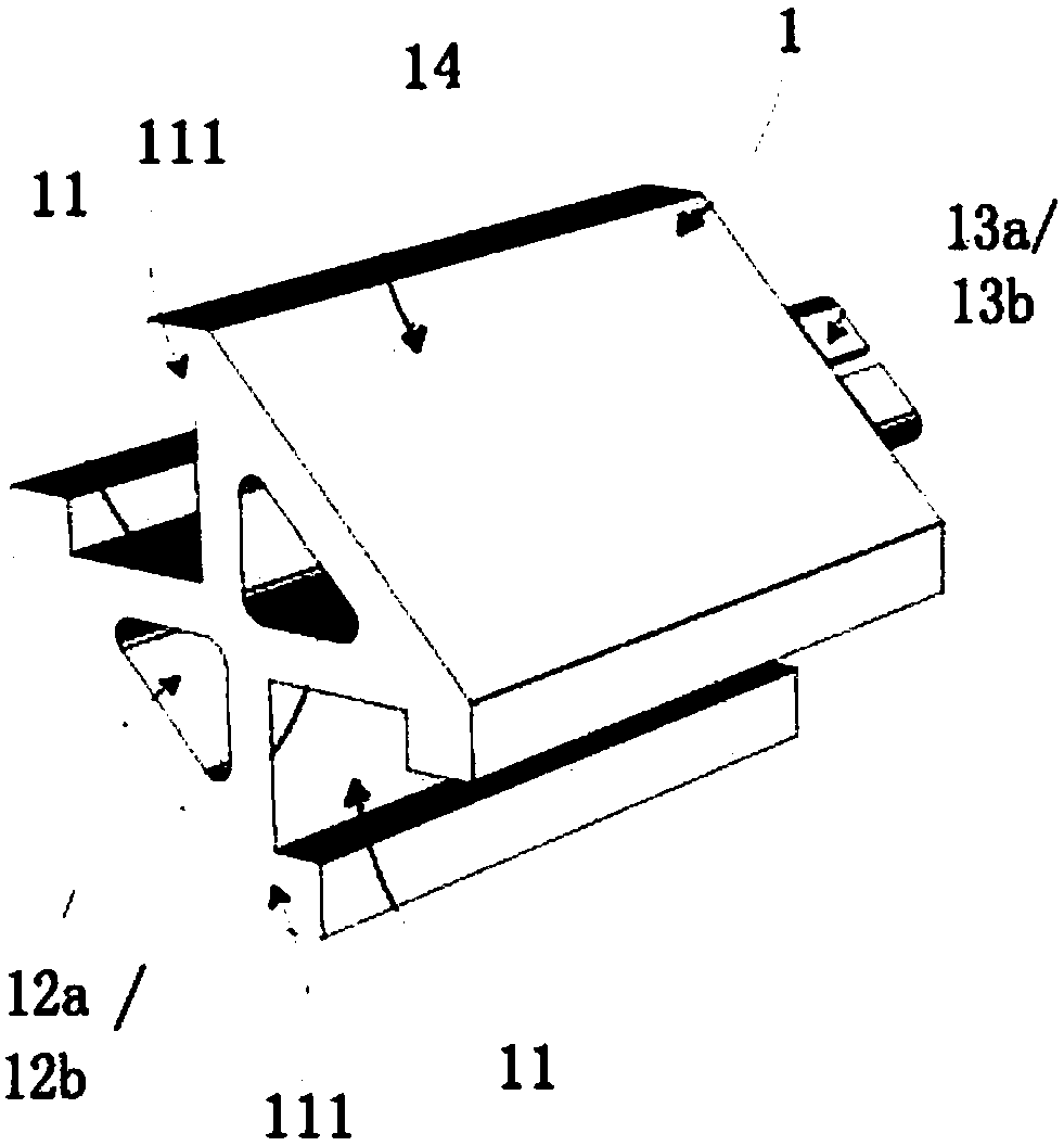
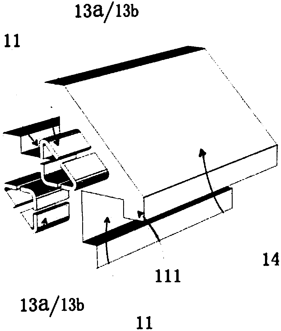
[0065] see figure 1 , which shows a schematic diagram of a three-dimensional structure of a connecting piece in the present invention, the connecting piece 1 includes a fixing groove 11, a first clamping groove 12a and a second clamping head 13b (or the second clamping groove 12b and the first clamping head 13a ); the fixed groove 11 is provided with a raised portion 111, and the raised portion 111 is set to cooperate with the groove 3 on the connected piece 2 so that the fixed groove 11 and the connected piece 2 are detachably clamped and fixed, the first The card slot 12a is configured to cooperate with the second card head 13b, so that the connectors 1 can be detachably inserted end-to-end through the card slot and the card head. figure 1 shows a schematic diagram of the three-dimensional structure viewed from the side of the card slot, figure 2 A schematic diagram of the three-dimensional structure viewed from the chuck head side is shown. In this embodiment, there are ...

Embodiment 3

[0067] see Figure 5 , which shows a schematic three-dimensional structural diagram of an assembly in the present invention, the assembly includes a connecting piece 1 and a connected piece 2; There is a groove 3, and a protrusion 111 is arranged in the fixing groove 11, and the protrusion 111 is set to cooperate with the groove 3 on the connected part 2 so that the fixing groove 11 and the connected part 2 are detachably clamped and fixed , the card slot is set to cooperate with the card head, so that the connectors 1 can be detachably plugged end-to-tail with the card head through the card slot. In this embodiment, each connecting piece 1 has two fixing grooves 11 , each of which is clamped and fixed with one connected piece 2 . It should be understood that the number of fixing slots 11 is not limited to two, Figure 7 to Figure 12 A schematic cross-sectional view of the assembly is shown. As shown in the figure, several fixing grooves 11 may be provided on the connecting ...


PUM


Abstract

The invention discloses a connecting piece. The first end of the connecting piece has a first card head and/or a first card slot, and the second end has a second card slot and a second card slot detachably matched with the above-mentioned first end. /or the second clamping head; the connecting piece also includes a clamping portion, the clamping portion extends between the first end and the second end of the connecting piece along the axis of the connecting piece, and the clamping portion is configured to be clamped fixed on the connected part. The invention also discloses an assembly and an assembly method, mainly aiming at the difficult problem of splicing and forming technology among various boards in furniture, toys, and interior decoration, a set of simple and easy-to-use connectors is designed to replace the traditional mortise and tenon structure, It has the advantages of simple processing, high precision, strong standardization and convenient assembly and disassembly of products.

Description

technical field [0001] The invention relates to the field of connecting structures for furniture, toys and interior decoration, in particular to a connecting piece, an assembly piece and an assembly method. Background technique [0002] With the development of the furniture industry, people put forward higher requirements for the appearance and function of furniture, requiring furniture to be beautiful, environmentally friendly, durable and flexible, especially for people with limited housing conditions or narrow office environments, flexible and easy to disassemble Modular furniture is even more popular. Modular furniture is realized through the combination of connecting structures. Traditional furniture mostly adopts mortise and tenon structure, especially dovetail tenon structure is often used when the board surface is handed over. In modern furniture, the board surfaces are often fixedly connected by metal connectors. . However, there are certain defects in the existin...

Claims


Application Information

Patent Timeline
Patent Type & Authority Applications(China)
IPC IPC(8): F16B5/06
CPCF16B5/0607F16B2005/0678
Inventor 孙绍顺
Owner 孙绍顺
Why Eureka
Try Eureka