A terminal and method for controlling terminal temperature
A technology for controlling terminals and terminals, which is applied in the direction of using electric methods for temperature control, etc., and can solve problems such as ineffective control of terminal heating and limited range of battery charging current.
- Summary
- Abstract
- Description
- Claims
- Application Information
AI Technical Summary
Problems solved by technology
Method used
Image
Examples
Embodiment 1
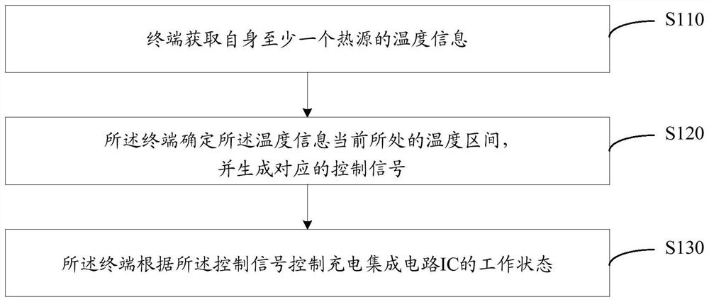
[0044] see figure 1 , which shows a flow of a method for controlling terminal temperature provided by an embodiment of the present invention, the method may include:
[0045] S110. The terminal acquires temperature information of at least one heat source of itself;
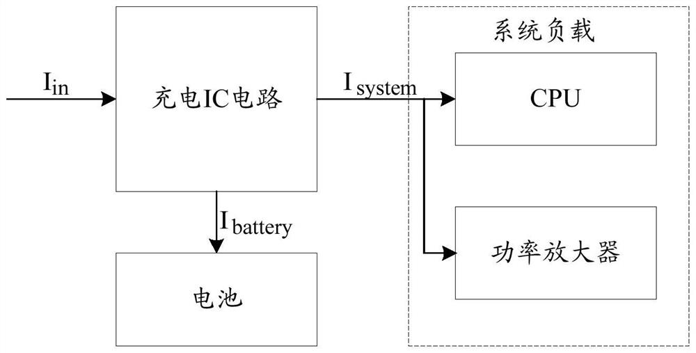
[0046] It should be noted that the heat source refers to a hardware unit that generates heat loss during operation of the terminal, and may mainly include but not limited to: a battery, a CPU, and a power amplifier. This embodiment of the present invention does not describe it in detail.
[0047] Exemplarily, the terminal obtains temperature information of at least one heat source of itself; the temperature information includes the temperature of the battery in the heat source and terminal temperature information; wherein, the method for obtaining the terminal temperature information may specifically include: the terminal detects the temperature of each heat source temperature, and acquire the terminal temperatu...
Embodiment 2
[0077] Based on the same technical concept as the foregoing embodiments, this embodiment describes the technical solutions of the foregoing embodiments through specific examples.
[0078] Take a certain Ti BQ series charging IC with dynamic path management as an example. The charging IC and the baseband processor are controlled by an I2C serial bus. The baseband processor can change the charging status and input current of the charging IC in real time through the I2C bus. size. The input voltage of the terminal charging IC is constant at 5V, the default maximum input current is 1000mA, and the thermal efficiency of the charging IC is 15%. The system load composed of the baseband circuit and the radio frequency circuit converts to a maximum operating current of 800mA at the input end, and the safe charging temperature of the battery used is 45°C.
[0079] When the system load is in the extreme working state, the battery charging current converted to the input terminal is 200mA...
Embodiment 3
[0087] Based on the same technical idea of the foregoing embodiments, see Figure 5 , which shows a terminal 50 provided by an embodiment of the present invention, the terminal 50 may include: a temperature information acquisition module 510, a control signal generation module 520, a charging IC control module 530, and a charging IC 540; wherein,
[0088] The temperature information acquisition module 510 is configured to acquire temperature information of at least one heat source of the terminal itself;
[0089] The control signal generation module 520 is configured to determine the temperature range where the temperature information is currently located, and generate a corresponding control signal;
[0090] The charging IC control module 530 is configured to control the working state of the charging IC 540 according to the control signal.
PUM
 Abstract
Description
Claims
Application Information
 - R&D
- Intellectual Property
- Life Sciences
- Materials
- Tech Scout
- Unparalleled Data Quality
- Higher Quality Content
- 60% Fewer Hallucinations
Browse by: Latest US Patents, China's latest patents, Technical Efficacy Thesaurus, Application Domain, Technology Topic, Popular Technical Reports.
© 2025 PatSnap. All rights reserved.Legal|Privacy policy|Modern Slavery Act Transparency Statement|Sitemap|About US| Contact US: help@patsnap.com


