Winnowing and dedusting rice drying equipment

A drying equipment and rice technology, applied in grain drying, drying gas arrangement, lighting and heating equipment, etc., can solve the problems of scorched particles, high processing cost, poor drying uniformity, etc., and achieve complete separation and structural design optimization. reasonable effect

Active Publication Date: 2018-03-13
合肥智权信息科技有限公司
View PDF9 Cites 4 Cited by
  • Summary
  • Abstract
  • Description
  • Claims
  • Application Information

AI Technical Summary

Problems solved by technology

The structure of the existing drying tower and its operating principle lead to the unsatisfactory drying effect, mainly as follows: 1. The drying uniformity is poor; 2. The free falling drying method of grain particles will produce a considerable amount of broken particles. It greatly affects the quality of grain processing and brings certain difficulties to normal storage; 3. The drying efficiency of the drying tower is relatively limited. Due to the retrograde between the drying air flow and the grain particles, the relative speed is high, and it is necessary to achieve large-scale drying. The operation index requires a high-temperature drying environment of 140-230°C, the particles are severely burnt, and the burnt rate is generally between 6-15%, especially in large-scale grain mechanized planting and grain production areas, such as corn planting areas. The maturity of corn is uneven, and the drying operation of the existing drying tower equipment will make the burnt situation more serious; 4. The processing cost of the existing drying method is high, and the processing cost is about 90 yuan / ton, and the grain reserve processing funds high pressure

Method used


Image

  • Winnowing and dedusting rice drying equipment

Examples


Embodiment Construction

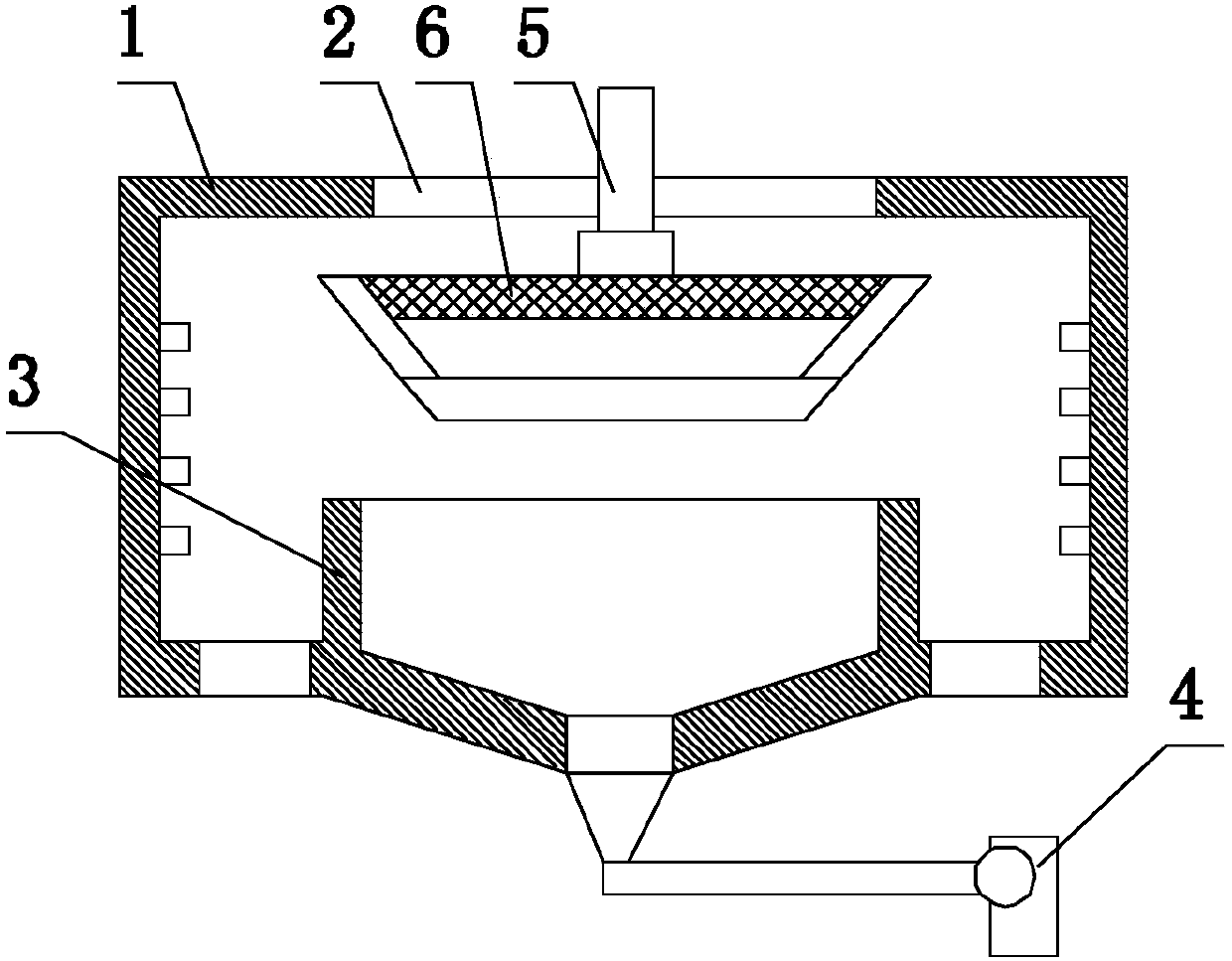
[0015] Such as figure 1 as shown, figure 1 It is a structural schematic diagram of a kind of wind separation and dedusting rice drying equipment proposed by the present invention.

[0016] refer to figure 1 , a kind of air selection and dust removal rice drying equipment proposed by the present invention, comprising: a housing 1, a flange 2, a material distributing device, an annular partition 3, a blower mechanism, an air induction mechanism 4, and a driving mechanism;

[0017] The inside of the shell 1 is provided with a receiving space with a top opening, the flange 2 is horizontally arranged at the opening, and the flange 2 is provided with an installation opening. The shell 1 includes an upper shell and a lower shell, and the inner wall of the upper shell is provided with a plurality of air blowing holes, through which the air blowing mechanism blows air into the accommodating space;

[0018] The distributing device comprises a feeding pipe 5 and a distributing pan 6, ...


PUM


Abstract

The invention discloses winnowing and dedusting rice drying equipment. A flange is horizontally arranged at the opening in the top of an outer shell; a plurality of blast holes are formed in the innerwall of an upper shell of the outer shell; a material distributing disc of a material distributing device is horizontally arranged in the upper shell of the outer shell; a feeding pipe is verticallyarranged at a mounting opening of the flange and the lower end of the feeding pipe is fixed to the material distributing disc; a material distributing hole is formed in the side wall of the feeding pipe; an annular partition plate is vertically arranged in a lower shell to divide the lower shell into a sundry cavity and a cereal cavity surrounding the sundry cavity; and an induced air port is formed in the bottom of the sundry cavity. By means of the optimal design of the winnowing and dedusting rice drying equipment, cereals entering the outer shell are distributed through the material distributing disc; under the action of the centrifugal force, cereal particles and straw dust impurities are separated, and meanwhile, air is blown inward through the blast holes in the outer shell, so thatthe cereal particles and the straw dust impurities are further separated, the cereal particles fall to the outer side of the annular partition plate, and the straw dust impurities fall into the annular partition plate, so that impurities are separated thoroughly from the cereals in the drying process.

Description

technical field [0001] The invention relates to the technical field of rice processing, in particular to a rice drying and dedusting equipment. Background technique [0002] Effectively controlling the moisture content of stored grain is the basic requirement for long-term safe storage of grain. At present, the most widely used mechanized grain drying equipment is mainly the drying tower, which is the mainstream product of my country's grain drying equipment. The drying tower uses the upward blowing hot dry air flow and the continuously falling grain particles to go against each other to dry the grain particles. The structure of the existing drying tower and its operating principle lead to the unsatisfactory drying effect, mainly as follows: 1. The drying uniformity is poor; 2. The free falling drying method of grain particles will produce a considerable amount of broken particles. It greatly affects the quality of grain processing and brings certain difficulties to normal...

Claims


Application Information

Patent Timeline
Patent Type & Authority Applications(China)
IPC IPC(8): B07B7/083B07B11/06B07B11/02F26B21/00
CPCF26B21/004B07B7/083B07B11/02B07B11/06F26B2200/06
Inventor 王爱龙陈盛杰
Owner 合肥智权信息科技有限公司
Why Eureka
Try Eureka