A hydraulic forging device

A hydraulic and forging machine technology, which is applied to forging/pressing/hammer devices, driving devices of forging presses, forging presses, etc., can solve the problems of workers' personal safety threats, workers' physical exertion, and low processing efficiency, and achieve saving Manpower and material resources, avoid turning over and feeding operations, and ensure the effect of personal safety

Active Publication Date: 2019-06-04
马鞍山平文锻造有限公司
View PDF7 Cites 0 Cited by
  • Summary
  • Abstract
  • Description
  • Claims
  • Application Information

AI Technical Summary

Problems solved by technology

[0003] In the prior art, in order to realize the forging process of the front and back sides of the workpiece, the workers need to use the clamp to clamp the heated blank into the lower die for forging process. After one side is processed, the worker needs to use the clamp to carry out 360 The other side is processed after being overturned at a high degree. This operation procedure consumes a lot of physical strength of the workers, and the processing efficiency is also low. It is also easy to pose a threat to the personal safety of the workers when the forging equipment is closed. Therefore, it is necessary to design a A new forging device not only has high work efficiency, but also can ensure the safety of workers

Method used


Image

  • A hydraulic forging device
  • A hydraulic forging device
  • A hydraulic forging device

Examples


Embodiment 1

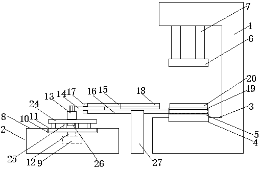
[0021] refer to Figure 1-4 , a hydraulic forging device, comprising a hydraulic forging machine 1 at the right end and an operating machine 2 at the left end, the lower part of the hydraulic forging machine 1 is a hydraulic workbench 3, and a groove 1 is arranged at the center of the surface of the hydraulic workbench 3 4. A lower mold table 5 is provided in the groove one 4, and an upper mold table 6 is arranged on the upper end of the lower mold table 5. The upper mold table 6 is connected to the hydraulic forging machine through a hydraulic push rod 7. 1 connected at the top;

[0022] The manipulator 2 includes a console 8 and a servo motor 9 located inside the console 8, a groove two 10 is provided at the center of the surface of the console 8, and a groove two 10 is provided in the groove two 10. Rotating plate 11, the rotating plate 11 is connected with the servo motor 9 through a rotating rod 12, a rotating cylinder 13 is provided above the rotating plate 11, and a ho...

Embodiment 2

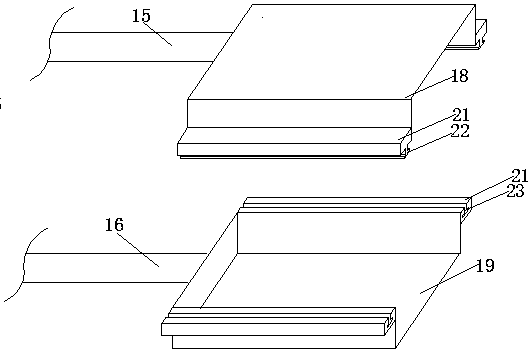
[0028] refer to Figure 5-6 , the difference from Embodiment 1 is that the upper package 18 is a separate upper and lower section structure, the upper telescopic rod 15 is welded on the left side of the lower section of the upper package 18, on the upper The left side of the two-stage structure of the package 18 is respectively provided with a protruding block 30, and the left and right ends of the protruding block 30 are respectively connected with a screw rod 31, and the bottom surface of the protruding block 30 at the lower end is in contact with the screw rod 31. A nut 32 is provided at the joint; this design can solve the problem that the package cannot adapt to workpieces of different heights, and only needs to use the screw rod 31 to adjust the distance between the upper and lower sections of the upper package 18. The structure is simple and the operation Convenience, the package does not have to be replaced several times.


PUM


Abstract

The invention provides a hydraulic forging device. The device comprises a right-end hydraulic forging machine and a left-end operating machine, the lower part of the hydraulic forging machine is provided with a hydraulic workbench, the central position of the surface of the hydraulic workbench is provided with a groove I, the groove I is internally provided with a lower mold table, the upper end of the lower mold table is provided with an upper mold table, and the upper mold table is connected with the top of the hydraulic forging machine through a hydraulic push rod. The hydraulic forging device has the beneficial effects that the device can be used for solving defects in the prior art, automatic feeding and overturning of a workpiece can be realized, artificial overturning and feeding operation can be avoided, and manpower and material resources are saved; the distance between upper packaging and lower packaging can be adjusted, and the forging of workpieces with different heights can be realized; in the forging process, a worker does not need to come close to the hydraulic forging machine, so that the personal safety of the worker is guaranteed.

Description

technical field [0001] The invention relates to the field of workpiece forging production, in particular to a hydraulic forging device. Background technique [0002] Forging is a processing method that uses forging machinery to apply pressure to metal blanks to cause plastic deformation to obtain forgings with certain mechanical properties, certain shapes and sizes. Forging can eliminate defects such as loose casting of metals during the smelting process. , optimize the microstructure, and because the complete metal flow line is preserved, the mechanical properties of forgings are generally better than castings of the same material. For important parts with high loads and severe working conditions in related machinery, forgings are mostly used, except for plates, profiles or weldments that can be rolled with simpler shapes. [0003] In the prior art, in order to realize the forging process of the front and back sides of the workpiece, the workers need to use the clamp to cl...

Claims


Application Information

Patent Timeline
Patent Type & Authority Patents(China)
IPC IPC(8): B21J9/02B21J9/12B21J13/10B21J13/12
CPCB21J9/02B21J9/12B21J13/10B21J13/12
Inventor 胡平
Owner 马鞍山平文锻造有限公司
Why Eureka
Try Eureka