Water draining and pressure relieving structure capable of realizing anti-floating

A technology of pressure relief structure and scupper hole, which is used in infrastructure engineering, protection devices, buildings, etc., to achieve the effect of reducing buoyancy, simple structure and avoiding piping

Pending Publication Date: 2018-03-13
HEFEI UNIV OF TECH
View PDF0 Cites 5 Cited by
  • Summary
  • Abstract
  • Description
  • Claims
  • Application Information

AI Technical Summary

Problems solved by technology

[0003] In order to overcome the deficiencies of the above-mentioned prior art, the purpose of the present invention is to solve the problem in the prior art of satisfying the purpose of anti-floating while simultaneously ensuring the strength and corrosion of the basement floor. Therefore, the present invention provides an anti-floating water and pressure relief structure

Method used


Image

  • Water draining and pressure relieving structure capable of realizing anti-floating
  • Water draining and pressure relieving structure capable of realizing anti-floating

Examples


Embodiment Construction

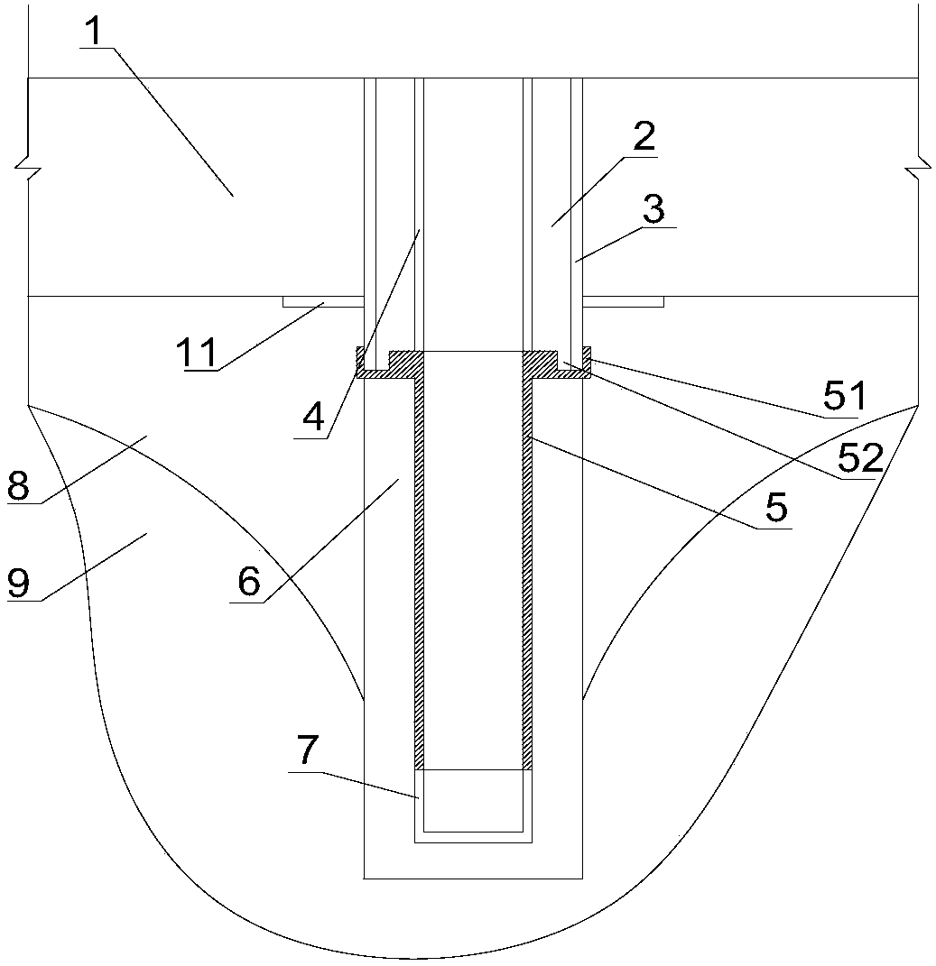
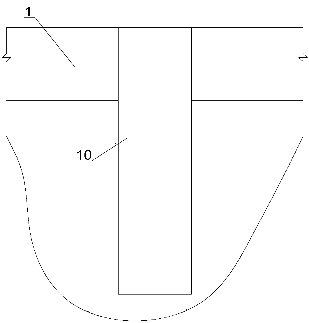
[0029] Such as Figure 1-2 As shown, an anti-floating water release and pressure relief structure is arranged in a drain hole 10 punched on the floor layer 1, and the drain hole 10 penetrates the floor layer 1 from top to bottom. The anti-floating water release and pressure relief structure includes the well wall pipe 4, the slow-expansion water-swelling water-swelling pipe 3, the filter pipe 5, the sedimentation pipe 7, and the water baffle 11, and the slow-expansion water-swelling water-stop pipe 3 is set on the well wall pipe 4. On the outside, a micro-expansion fine stone concrete layer 2 is arranged between the slow-expanding water-expanding water-stop pipe 3 and the well wall pipe 4. inside diameters match. The downward length of the slow-expansion type water-expandable water-stop pipe 3 is greater than the length of the well wall pipe 4, and the pipe thickness of the slow-expansion type water-expansion water-stop pipe 3 is not less than 200mm. The slow-expanding water...


PUM


Abstract

The invention discloses a water draining and pressure relieving structure capable of realizing anti-floating. The water draining and pressure relieving structure capable of realizing anti-floating comprises a well wall pipe and a slow expansion type hydro-expansive antipriming pipe. The slow expansion type hydro-expansive antipriming pipe is arranged outside the well wall pipe in a sleeving manner. A micro-expansionary fine aggregate concrete layer is arranged between the slow expansion type hydro-expansive antipriming pipe and the well wall pipe. The outer diameter of the slow expansion typehydro-expansive antipriming pipe corresponds to the inner diameter of a water draining hole in which the slow expansion type hydro-expansive antipriming pipe is located. The structure has the advantages that when water leaks out of the well wall pipe, both the slow expansion type hydro-expansive antipriming pipe and the micro-expansionary fine aggregate concrete layer expand, and at the moment, the gap between the slow expansion type hydro-expansive antipriming pipe and the inner side wall of the water draining hole decreases, so that the corrosion to a floor layer due to the outflow, from theexterior of a well wall to the floor layer, of the water under the floor layer can be effectively prevented, the strength of the floor layer is lowered and the function of anti-floating is realized;the water under the floor layer is drained out through the well wall pipe, so that the buoyancy which is applied to the floor layer by the water is reduced and the function of pressure relieving is realized.

Description

technical field [0001] The invention relates to the technical field of water release, pressure relief and anti-floating in underground engineering, in particular to an anti-floating water and pressure relief structure. Background technique [0002] For underground structural engineering with deep buried depth and high anti-floating water level, if the anti-floating structure does not meet the requirements and the problem is not properly dealt with, it may cause serious problems such as overall or partial floating of the structure, cracking of the bottom plate, and the destruction of the underground structure. The most commonly used solution in the face of anti-floating problems is to increase counterweight, anti-floating anchor rods and anti-floating piles. The counterweight method is more convenient to implement, but it has many limitations, and it is at the expense of considerable underground space; the uplift pile is conducive to exerting the strength and deformation char...

Claims


Application Information

Patent Timeline
Patent Type & Authority Applications(China)
IPC IPC(8): E02D31/10E02D31/12
CPCE02D31/10E02D31/12
Inventor 姚华彦张子涵吴平郭杨
Owner HEFEI UNIV OF TECH
Why Eureka
Try Eureka