Underpinning structure and underpinning construction method for shock isolation and reinforcing of existing building

A technology of existing buildings and construction methods, applied in building construction, construction, building maintenance, etc., can solve the problems of construction cost, high material cost, hidden danger of superstructure safety, hindering the application of seismic isolation technology, etc., and achieve less material consumption. , The bracket structure is simple, easy to carry and reuse.

Pending Publication Date: 2018-03-13
南京分震建筑科技有限公司
View PDF7 Cites 1 Cited by
  • Summary
  • Abstract
  • Description
  • Claims
  • Application Information

AI Technical Summary

Problems solved by technology

[0006] These two underpinning structures and underpinning methods mainly have the following three problems: (1) The consumption of materials is large, and a large amount of steel is consumed for pulling the screw rods, shaped steel beams and columns; The concrete can only be dismantled after reaching the design strength; (3) the cost is high, and the construction cost and material cost are high; (4) the safety risk is high, and all the column bottoms are connected in this way. In case of horizontal shaking, the upper structure may be safe. Hidden danger
[0007] The above defects of the existing underpinning technology have seriously hindered the application of seismic isolation technology in seismic reinforcement, and it is urgent to develop an underpinning method suitable for the characteristics of seismic isolation technology

Method used


Image

  • Underpinning structure and underpinning construction method for shock isolation and reinforcing of existing building
  • Underpinning structure and underpinning construction method for shock isolation and reinforcing of existing building

Examples


Embodiment Construction

[0035] The following will clearly and completely describe the technical solutions in the embodiments of the present invention with reference to the accompanying drawings in the embodiments of the present invention. Obviously, the described embodiments are only some, not all, embodiments of the present invention. The following description of at least one exemplary embodiment is merely illustrative in nature and in no way taken as limiting the invention, its application or uses. Based on the embodiments of the present invention, all other embodiments obtained by persons of ordinary skill in the art without creative efforts fall within the protection scope of the present invention. The relative arrangements, expressions and numerical values ​​of components and steps set forth in these embodiments do not limit the scope of the present invention unless specifically stated otherwise. At the same time, it should be understood that, for the convenience of description, the sizes of the...


PUM


Abstract

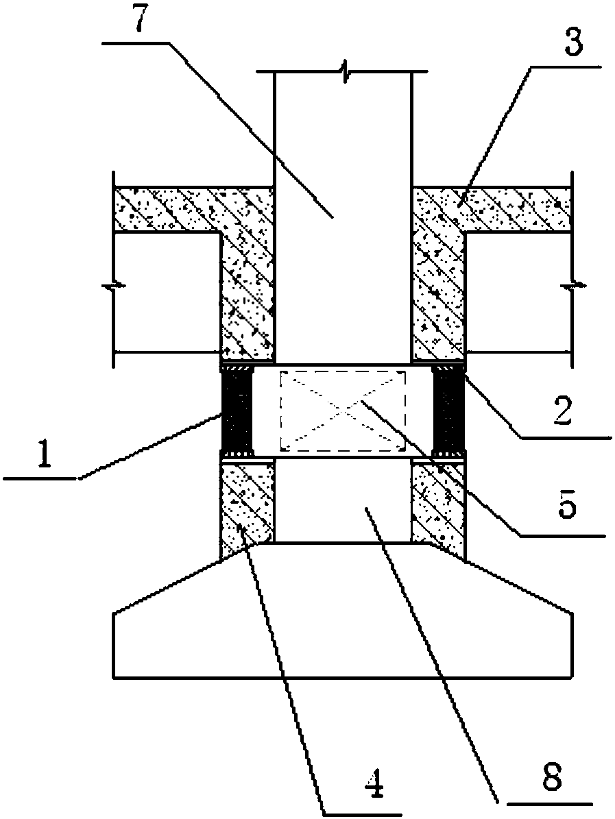
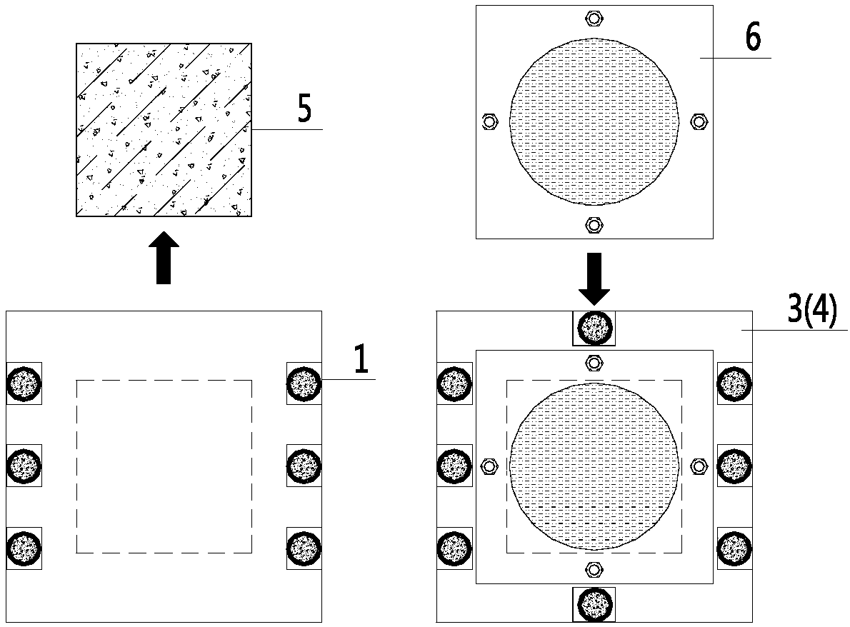
The invention discloses an underpinning structure and an underpinning construction method for shock isolation and reinforcing of an existing building. The underpinning structure comprises an upper structure, a lower structure and a plurality of supporting columns; the upper structure is located on the upper portion of the mounting position of a shock isolation supporting seat of the existing building, and the lower structure is located on the lower portion of the mounting position of the shock isolation supporting seat of the existing building; and the multiple supporting columns are located on the outer side of the mounting position of the shock isolation supporting seat, and the two ends of the multiple supporting columns tightly abut against the upper structure and the lower structure correspondingly. During construction, after the supporting columns abut tightly, column concrete on the mounting position of the shock isolation supporting seat is cut, the shock isolation supporting seat is mounted, gaps between the shock isolation supporting seat and the upper structure as well as the lower structure are filled, grouting and compaction are conducted, and after the concrete strength meets requirements, the supporting columns are removed. Therefore, according to the underpinning structure and the underpinning construction method for shock isolation and reinforcing of the existing building, the underpinning structure utilizes an original structure component, model selection is simple, the underpinning construction method is convenient to construct, and the construction period is short.

Description

technical field [0001] The invention belongs to the technical field of building structure transformation, and relates to an underpinning structure, which is mainly used for underpinning of load-bearing frame columns in the seismic isolation and reinforcement of existing buildings. [0002] The present invention also relates to an underpinning construction method based on the above underpinning structure. Background technique [0003] Underpinning technology is often used in the seismic isolation and reinforcement of existing buildings. There are usually two underpinning structures and methods: one is the "steel opposite pull screw method", and the other is the "steel-clad joist method". [0004] The "Sectional Steel Pulling Screw Method" was invented by Southeast University and applied in the translation of Jiangnan Hotel and other projects. The underpinning of seismic isolation reinforcement works also follows this approach. The bracket system is based on the "section st...

Claims


Application Information

Patent Timeline
Patent Type & Authority Applications(China)
IPC IPC(8): E04G23/06E04H9/02
CPCE04G23/06E04H9/027
Inventor 鲁风勇李小敏
Owner 南京分震建筑科技有限公司
Why Eureka
Try Eureka