Marine drill pipe connector

A drill pipe joint and marine technology, applied in the direction of drill pipe, drill pipe, drilling equipment, etc., can solve the problems of reducing ROP, increasing friction coefficient, increasing torque, etc., to avoid local erosion, reduce joint wear, avoid deposition effect

Inactive Publication Date: 2018-03-13
宁波市镇海百硕机械科技有限公司
View PDF0 Cites 0 Cited by
  • Summary
  • Abstract
  • Description
  • Claims
  • Application Information

AI Technical Summary

Problems solved by technology

Therefore, it is easy to deposit debris, increase the pressure of the offshore drill pipe, accelerate the wear of the offshore drill pipe, and cause the breakage of the offshore drill pipe in severe cases, resulting in drilling accidents, reduced drilling efficiency, and increased drilling costs.
[0007] The solid phases such as cuttings carried in the drilling fluid are easy to block the oil and gas channels. When the drilling fluid pressure is higher than the formation pressure, the drilling fluid penetrates into the formation, and the solid phases such as cuttings, which are smaller than the oil and gas passages in the formation, will go deeper, forming blockages and leaking formations. It makes the drill bit easy to pack mud, pull out the piston, induce blowout, and cause pressure surge when running down the drill, causing well leakage and eventually polluting the oil layer
And a large amount of debris deposition will reduce the ROP
[0008] If the solid phase such as cuttings in the drilling fluid cannot be effectively removed, the mud cake will become loose and thick, resulting in large water loss and easy wall collapse; the hole becomes smaller and the pipe is easy to stick; causing pressure differential sticking
A large number of solid phase deposits such as cuttings will increase the friction coefficient and torque, which will increase power consumption, and easily cause drill tool accidents and reduce the life of the drill tool

Method used


Image

  • Marine drill pipe connector
  • Marine drill pipe connector
  • Marine drill pipe connector

Examples


Embodiment Construction

[0022] The present invention will be described in further detail below in conjunction with the accompanying drawings.

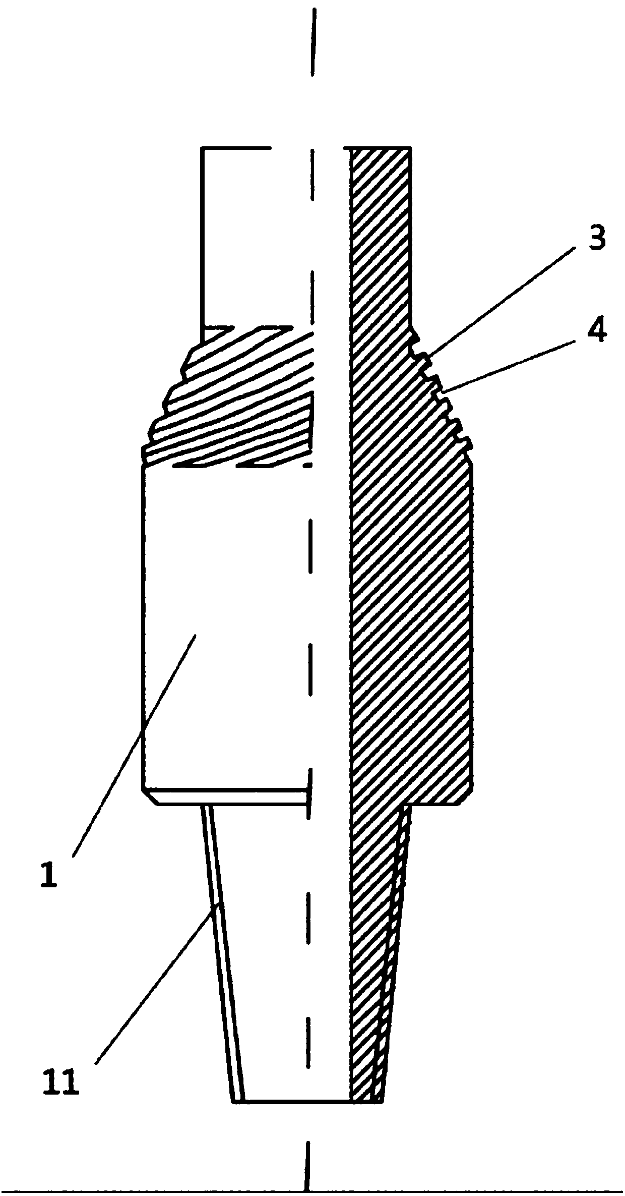
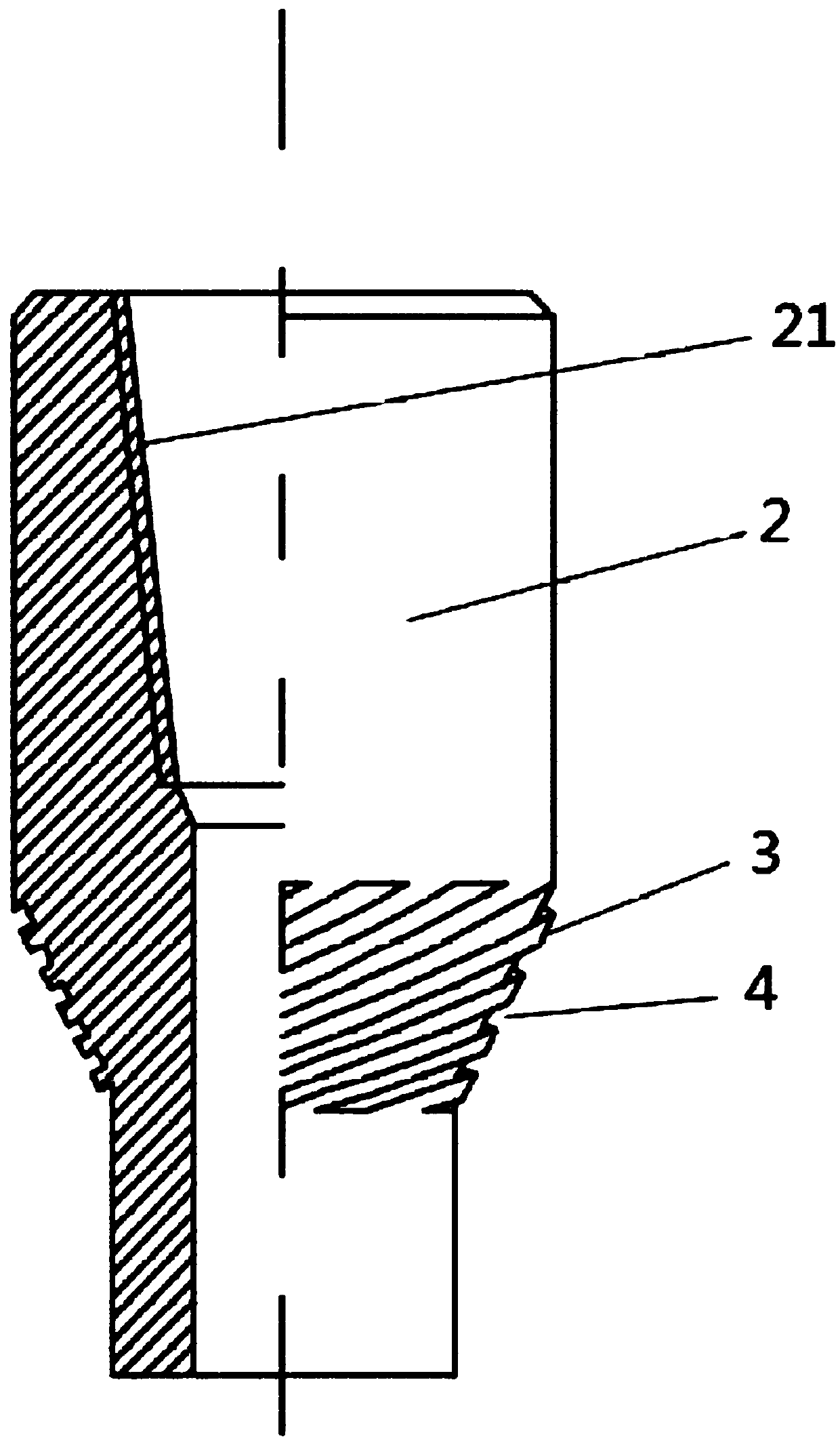
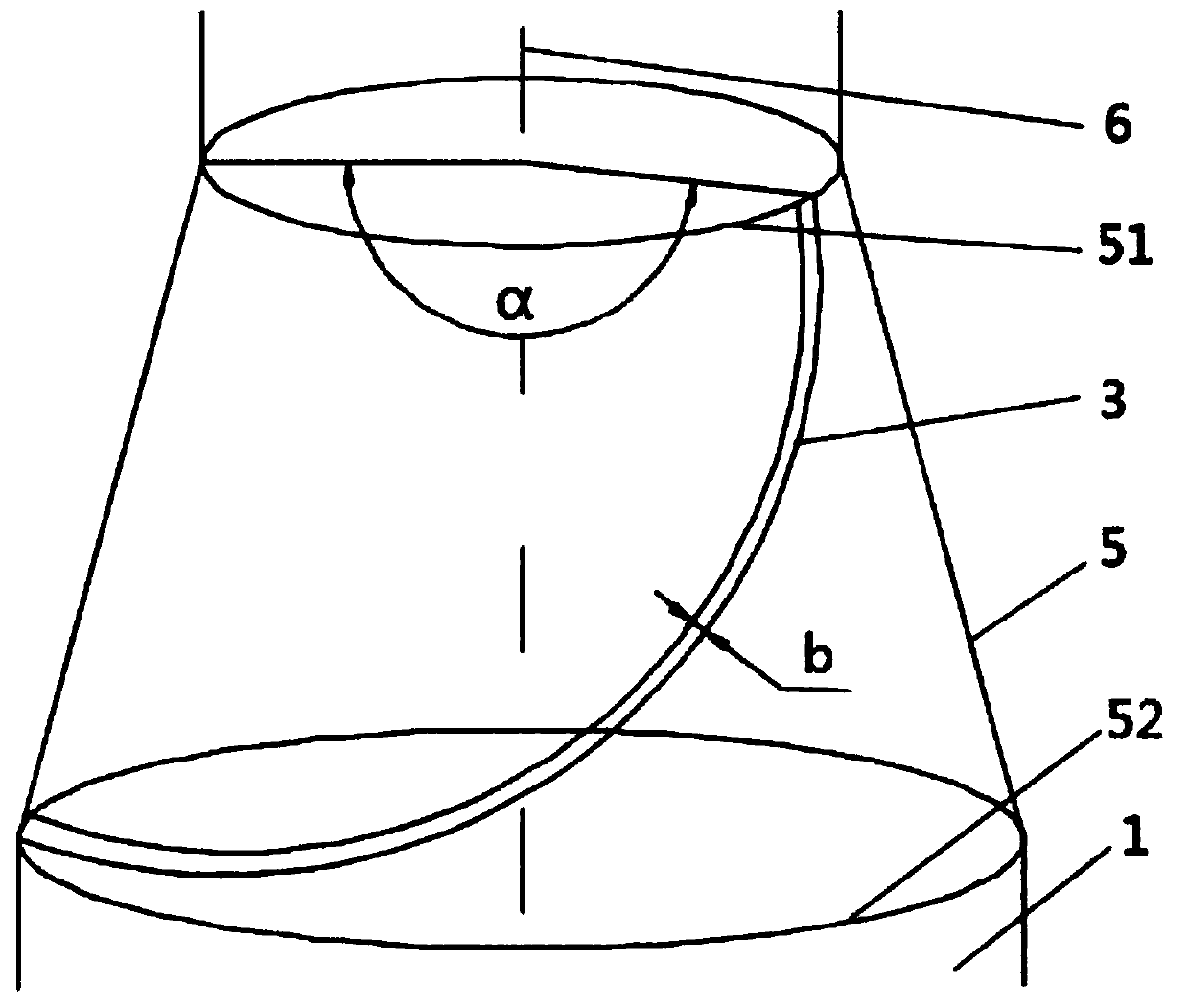
[0023] A marine drill pipe joint, such as figure 1 , figure 2 , image 3 , Figure 4 As shown, it includes: a male connector 1 and a female connector 2. The male connector 1 and the female connector 2 have external threads 11 and internal threads 21 that match each other. One end of the internal thread 21 is provided with a tapered shoulder 5, and several reinforcing ribs 3 of spiral structure are arranged at intervals on the tapered shoulder 5, and a spiral groove 4 is formed between adjacent reinforcing ribs 3. The spiral extension of the reinforcing rib 3 along the outer surface of the tapered shoulder 5 may be clockwise or counterclockwise, which is selected according to actual needs.

[0024] The transverse cross-sectional shape of the reinforcing rib 3 can be various, such as triangle, trapezoid, etc., and the preferred transverse cross-section of ...


PUM

PropertyMeasurementUnit
Thicknessaaaaaaaaaa

Abstract

The invention discloses a marine drill pipe joint, which comprises a male joint and a female joint. The male joint and the female joint have external threads and internal threads that match each other. One end of the threaded end is provided with a tapered shoulder, and a plurality of reinforcing ribs of spiral structure are arranged at intervals on the tapered shoulder, and spiral grooves are formed between adjacent reinforcing ribs. The marine drill pipe joint of the present invention is provided with a number of helical ribs and spiral grooves at intervals on the tapered shoulder, so that the marine drill pipe joint has high torsional strength, large load capacity, and uniform stress distribution, which meets the requirements of marine drill pipe drilling. High torsional requirements for ultra-deep wells. In addition, the ribs and spiral grooves also have the advantages of accelerating the circulation of drilling fluid and improving the ability to resist erosion and wear, which can prevent premature wear and failure of offshore drill pipes, thereby prolonging the life of drill pipes, improving drilling efficiency, shortening drilling cycles, and reducing drilling costs.

Description

technical field [0001] The invention relates to the technical field of offshore oil and gas exploration equipment, in particular to an offshore drill pipe joint. Background technique [0002] Drill pipe is an important tool for drilling work, and it is an important part of the drill string. During the drilling process, the drill pipe plays an important role, such as transporting drilling fluid to the bottom of the well, transmitting torque to the drill bit, tripping the drill bit, dealing with downhole accidents, testing, etc. [0003] In the process of offshore drilling, different drilling fluids form different dispersion systems and play different roles. From a physical and chemical point of view, drilling fluid is a multiphase unstable system. In order to meet the requirements of the drilling process and improve the performance of the drilling fluid, various additives are often added to the drilling fluid. During the circulation process, the drilling fluid cannot alway...

Claims


Application Information

Patent Timeline
IPC IPC(8): E21B17/042
CPCE21B17/042
Inventor 王海燕
Owner 宁波市镇海百硕机械科技有限公司
Why Eureka
Try Eureka