Exhaust fan

An exhaust fan and box technology, which is applied to the components of the pumping device for elastic fluid, non-variable-capacity pumps, pump devices, etc., can solve the problems of low efficiency and high noise of the exhaust fan, and reduce the The effect of noise, low noise and high efficiency

Pending Publication Date: 2018-03-13
ZHONGSHAN BROAD OCEAN
View PDF0 Cites 5 Cited by
  • Summary
  • Abstract
  • Description
  • Claims
  • Application Information

AI Technical Summary

Problems solved by technology

[0005] The purpose of the present invention is to provide an exhaust fan, which

Method used


Image

  • Exhaust fan
  • Exhaust fan
  • Exhaust fan

Examples


Embodiment 1

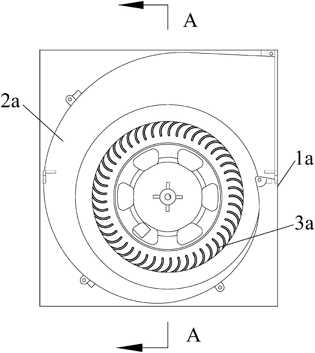
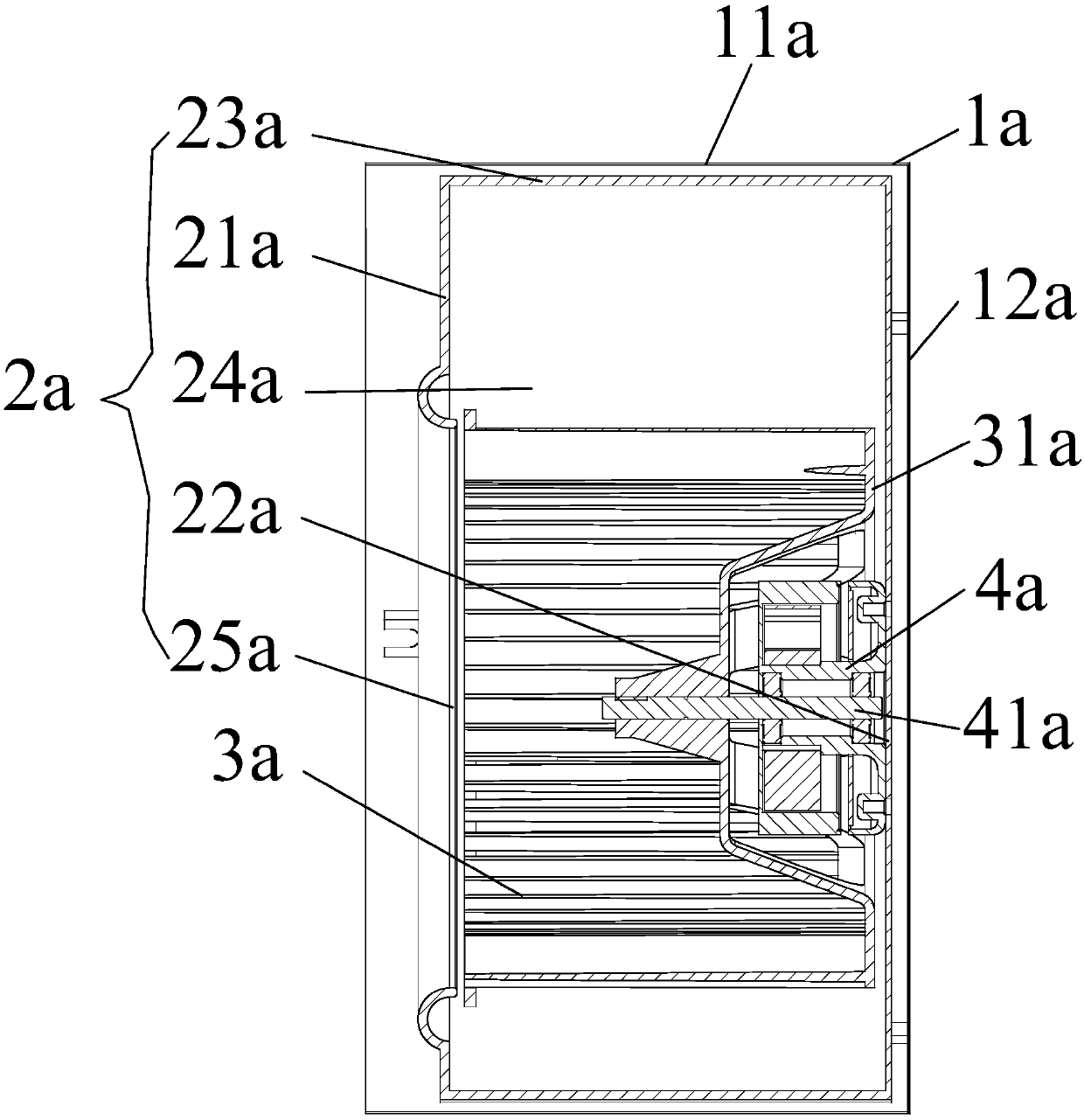
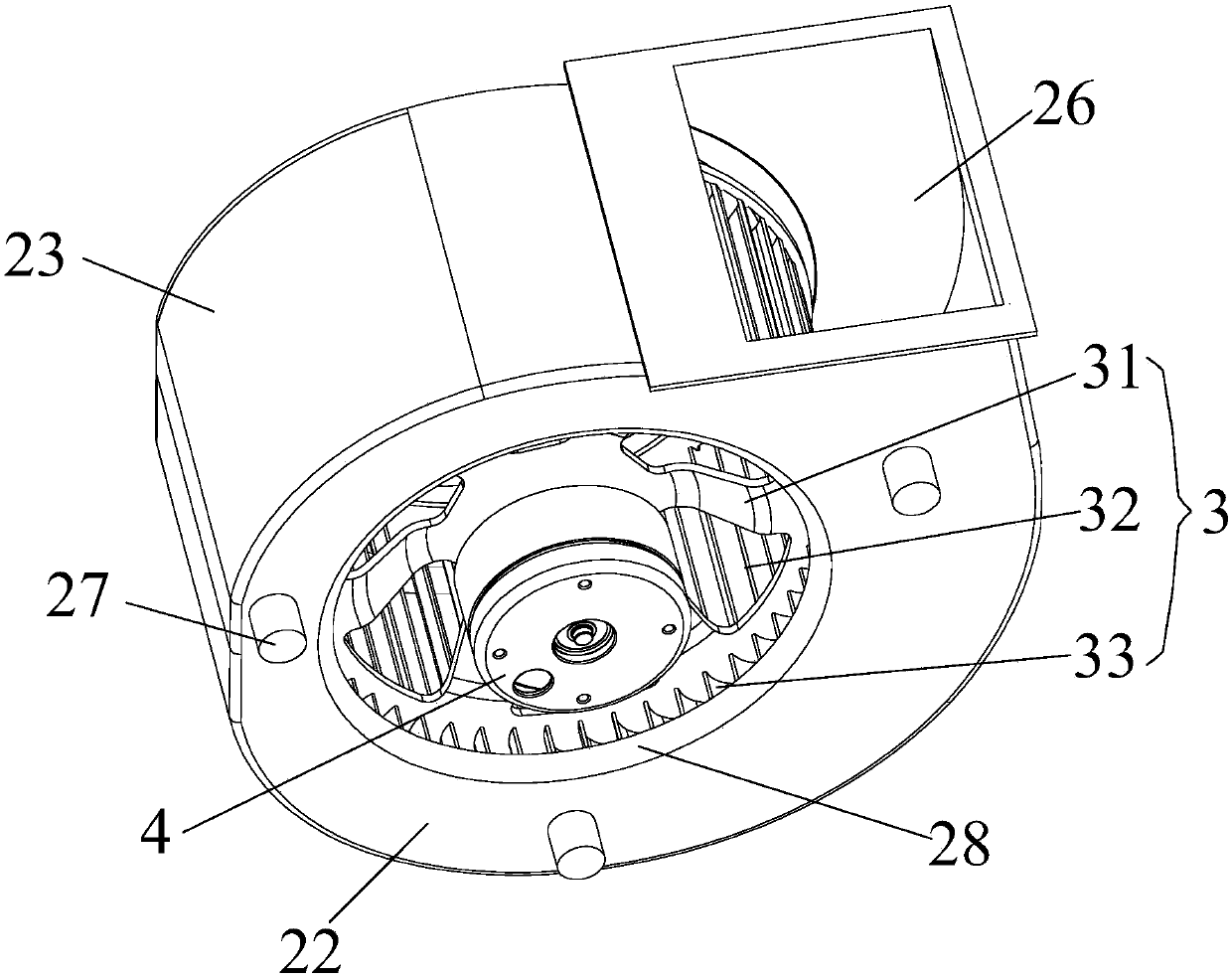
[0032] Such as Figure 3 to Figure 8 As shown, what this embodiment provides is an exhaust fan, including a box body 1 and a volute fan. The box body 1 includes a cover plate 11, a side plate 12 and a bottom plate 13. Bottom plate 13 encloses accommodating cavity, and described volute fan includes volute 2, wind wheel 3 and motor 4, and described volute 2 is fixed in the accommodating cavity of box body 1, and described volute 2 comprises front end Plate 21, rear end plate 22 and side plate 23 connected between front end plate 21 and rear end plate 22, front end plate 21, rear end plate 22 and side plate 23 enclose cavity 24, wind wheel 3 is arranged in the cavity 24, the cover plate 11 is provided with a slit 110, the side plate 12 is provided with an opening 120, the front end plate 21 is provided with a first air inlet 25, and the side panel 23 is provided with an air outlet 26, so The slit 110, the first air inlet 25, the cavity 24, the air outlet 26 and the opening 120 c...


PUM


Abstract

The invention discloses an exhaust fan, which includes a box body and a volute fan. The box body includes a cover plate, a side plate and a bottom plate. The motor and the volute are fixed in the housing cavity of the box. The volute includes a front end plate, a rear end plate and a side plate. The front end plate, the rear end plate and the side plates form a cavity. There are slits on the top, openings on the side panels, first air inlets on the front end, and air outlets on the side panels. The slits, first air inlets, cavities, air outlets, and openings are connected to form a first ventilation channel. , the rear end plate is provided with a second air inlet, the air channel is formed between the side plate and the side plate, the flow channel is formed between the rear end plate and the bottom plate, the gap, the air channel, the flow channel, the second air inlet, the cavity, The air outlet and the opening are connected to form a second ventilation channel, and an additional ventilation channel increases the air inlet area, improves the efficiency, and improves the noise.

Description

Technical field: [0001] The invention relates to an exhaust fan. Background technique: [0002] Such as figure 1 and 2 As shown, the existing exhaust fan includes a box body 1a and a volute fan. The box body 1a includes a cover plate, a side plate 11a and a bottom plate 12a. The volute fan includes a volute 2a, a wind wheel 3a and a motor 4a, the volute 2a is fixed in the housing chamber of the box 1a, the volute 2a includes a front end plate 21a, a rear end plate 22a and The side plate 23a that is connected between the front end plate 21a and the rear end plate 22a, the front end plate 21a, the rear end plate 22a and the side plate 23a surround a cavity 24a, the wind wheel 3a is arranged on the inside of the cavity 24a, and the cover plate is provided with The slit, the side plate 11a is provided with an opening, the front end plate 21a is provided with an air inlet 25a, and the side panel 23a is provided with an air outlet, the slit, the air inlet 25a, the cavity 24a, t...

Claims


Application Information

Patent Timeline
IPC IPC(8): F04D25/12F04D29/00F04D29/28F04D29/42F04D29/66
CPCF04D25/12F04D29/002F04D29/281F04D29/4226F04D29/424F04D29/661
Inventor 林炎虎黎健辉王凤琪
Owner ZHONGSHAN BROAD OCEAN
Why Eureka
Try Eureka