
Gas storage device and adjustment method for improving gas storage efficiency

A gas storage device and efficiency technology, which is applied in the field of gas storage devices to improve gas storage efficiency, can solve problems such as low gas storage efficiency, improve cycle efficiency and volumetric efficiency, improve energy storage efficiency and economic benefits, and improve cycle efficiency Effect

Active Publication Date: 2018-10-30
TSINGHUA UNIV
View PDF7 Cites 0 Cited by
  • Summary
  • Abstract
  • Description
  • Claims
  • Application Information

AI Technical Summary

Problems solved by technology

[0017] The purpose of the present invention is to provide a gas storage device and method for improving gas storage efficiency, and to solve the problem of low gas storage efficiency due to temperature and pressure changes during the charging and discharging process of high-pressure gas

Method used


Image

  • Gas storage device and adjustment method for improving gas storage efficiency
  • Gas storage device and adjustment method for improving gas storage efficiency

Examples


Embodiment ( 1

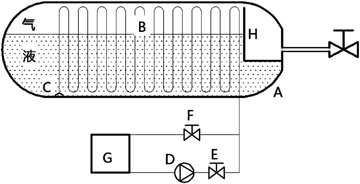
[0084] like figure 1 As shown, the embodiment of the present invention provides a horizontal gas storage device, including a horizontal pressure vessel A, a heat exchanger coil B and a liquid pressurization system.

[0085] Further, a liquid baffle H is provided at the outlet of the horizontal pressure vessel A.

[0086] The heat exchanger coil B is fixedly installed in the air cavity of the horizontal pressure vessel A.

[0087] At the same time, one end of the heat exchanger coil B is connected to the outside through the wall of the horizontal pressure vessel A, and the other end is an open liquid discharge port C.

[0088] Further, the drain port C is located at the bottom of the air chamber of the horizontal pressure vessel A.

[0089] The liquid boosting system includes a liquid boosting pump D, a pipeline valve E, a liquid return bypass valve F, a liquid working medium source G and a control module.

[0090] Further, the liquid pressurization system is installed outsi...

Embodiment ( 2

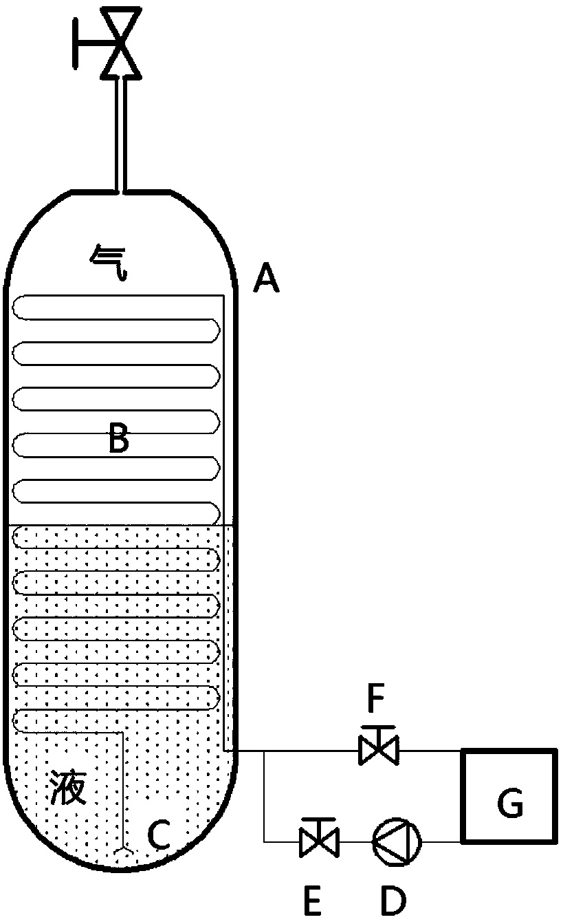
[0103] like figure 2 As shown, the embodiment of the present invention provides a vertical gas storage device, including a gas storage chamber and a liquid pressurization system.

[0104] The gas storage chamber is a vertical pressure vessel A.

[0105] The heat exchange system is heat exchanger coil B.

[0106] Further, the heat exchanger coil B is fixedly installed in the air cavity of the vertical pressure vessel A.

[0107] At the same time, one end of the heat exchanger coil B is connected to the outside through the wall of the vertical pressure vessel A, and the other end is an open liquid discharge port C.

[0108] Further, the drain port C is located at the bottom of the air cavity of the vertical pressure vessel A.

[0109] The liquid boosting system includes a liquid boosting pump D, a pipeline valve E, a liquid return bypass valve F, a liquid working medium source G and a control module.

[0110] Further, the liquid pressurization system is installed outside th...


PUM


Abstract

The invention relates to the technical field of gas compression and energy storage, in particular to a high-pressure gas storage device for improving the gas storage efficiency by adjusting the gas storage temperature and an adjustment method. The high-pressure gas storage device comprises a gas storage chamber and a supercharging heat exchange system; the gas storage chamber is provided with a gas charging and discharging port through which gas passes in and out; a heat exchanger of the supercharging heat exchange system is located in the gas storage chamber; a supercharging heat exchange working medium pipeline is located outside the gas storage chamber; a first working medium flowing end of the heat exchanger is connected with the supercharging heat exchange working medium pipeline; a connecting pipeline formed by the first working medium flowing end and the supercharging heat exchange working medium pipeline penetrates through a gas storage chamber housing in a sealed manner; an open type liquid outlet is formed in a second working medium flowing end of the heat exchanger; the supercharging heat exchange working medium pipeline comprises a liquid type heat exchange working medium source and more than one branch; and the liquid type heat exchange working medium source is connected with the first working medium flowing end through the more than one branch. With the adoption of the supercharging heat exchange working medium pipeline, a liquid type heat exchange working medium is conveyed into or out of the gas storage chamber according to the gas temperature and pressure in the gas storage chamber, the liquid type heat exchange working medium carries out heat exchange with the gas, the gas temperature is basically maintained constant, and the pressure is not lower thangas supply pressure.

Description

technical field [0001] The invention relates to the technical field of gas compression and energy storage, in particular to a gas storage device and a saving method for improving gas storage efficiency. Background technique [0002] High-pressure gas is widely used in industrial production and daily life. Especially in large-scale industrial production applications, it is necessary to frequently fill and deflate large-capacity high-pressure gas storage tanks. At the same time, an emerging energy storage technology, namely compressed air energy storage technology, has begun to be promoted and applied globally. This technology uses air as the energy storage medium, air compression is the energy storage process, and air expansion is the energy release process; the compressed air energy storage system generally works in a daily cycle mode, so in the compressed air energy storage system, the gas storage device needs to be frequently The inflation and deflation cycle. [0003] I...

Claims


Application Information

Patent Timeline
Patent Type & Authority Patents(China)
IPC IPC(8): F17C13/00F17C13/02
CPCF17C13/002F17C13/021F17C13/025F17C13/026F17C2227/0309F17C2227/0341F17C2227/0372F17C2227/04F17C2250/043F17C2250/0439F17C2250/0678F17C2250/072
Inventor 梅生伟薛小代陈来军卢强
Owner TSINGHUA UNIV
Learn More