
System for managing pressure in underground cryogenic liquid storage tank and method for the same

A low-temperature liquid and land management technology, applied in the field of pressure systems, can solve the problems of storage tanks being inconveniently buried underground, and achieve the effects of effective pressurization, prevention of storage tank collapse, and extended service life

Pending Publication Date: 2021-12-17
CHNA ENERGY INVESTMENT CORP LTD +1
View PDF10 Cites 1 Cited by
  • Summary
  • Abstract
  • Description
  • Claims
  • Application Information

AI Technical Summary

Problems solved by technology

[0007] The object of the present invention is to provide a system and method for managing the pressure in an underground cryogenic liquid storage tank, so as to solve the defect that the existing storage tanks are inconvenient to be buried underground

Method used


Image

  • System for managing pressure in underground cryogenic liquid storage tank and method for the same
  • System for managing pressure in underground cryogenic liquid storage tank and method for the same
  • System for managing pressure in underground cryogenic liquid storage tank and method for the same

Examples


no. 1 example

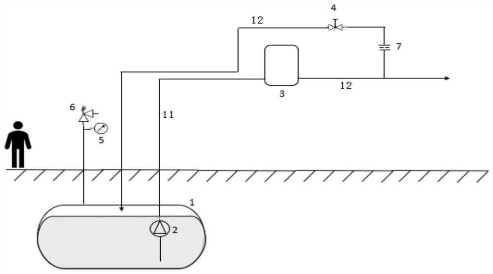
[0050] Such as figure 1 As shown, the first embodiment discloses a system for managing pressure in an underground cryogenic liquid storage tank, comprising: storage tank 1, internal pump 2, evaporator 3, control valve 4, pressure sensor 5, pressure relief valve 6. Restrictor 7, liquid discharge pipeline 11 and steam delivery pipeline 12. Wherein, the storage tank 1 is used to accommodate cryogenic liquid, and there is a headspace above the cryogenic liquid in the storage tank 1, and the headspace is suitable for containing vapor.

[0051] An internal pump 2 is arranged in the storage tank 1, and the internal pump 2 is preferably a submersible pump, which is located below the liquid level of the cryogenic liquid. Alternatively, the internal pump 2 may also be a self-priming pump, the inlet of which is located below the liquid level of the cryogenic liquid. The internal pump 2 of the present invention is not limited to a submersible pump or a self-priming pump, and may also be...

no. 2 example

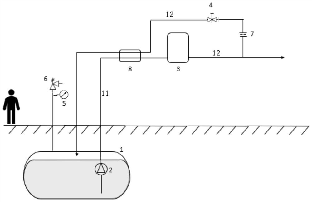
[0063] Such as figure 2 As shown, the second embodiment discloses a system for managing the pressure in an underground cryogenic liquid storage tank, which differs from the first embodiment mainly in the upstream of the evaporator 3 and the downstream of the control valve 4 At the same time, the same heat exchanger 8, preferably a regenerative heat exchanger, is compactly arranged on the pipeline.

[0064] The heat exchanger 8 can cool the warm vapor evaporated by the evaporator 3 by means of a cold high pressure discharge therein or a part of the low temperature liquid discharge pumped by the internal pump 2 upstream of the evaporator 3 . In this way, the thermal load in the storage tank 1 is minimized. In addition, since part of the sensible heat of the cryogenic liquid is removed, the rate of pressure increase in the storage tank 1 is effectively controlled.

no. 3 example

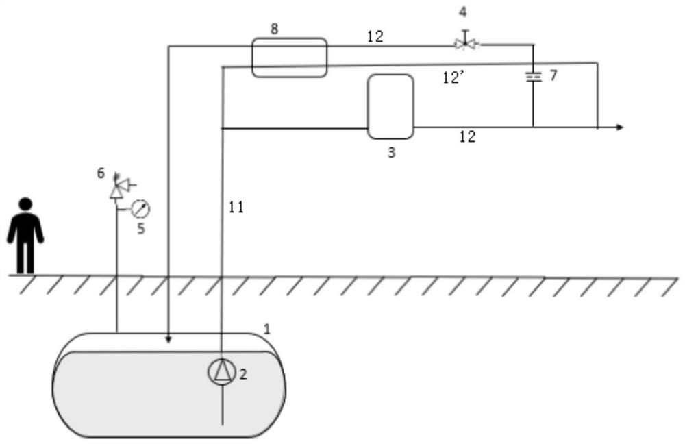
[0066] Such as image 3 As shown, the third embodiment discloses a system for managing the pressure in an underground cryogenic liquid storage tank, the difference from the second embodiment is mainly in the pipeline 12' parallel to the evaporator 3 and the The pipeline downstream of the control valve 4 is also compactly provided with the same heat exchanger 8, preferably a regenerative heat exchanger.

[0067] The heat exchanger 8 can cool the warm vapor evaporated by the evaporator 3 by using part of the cryogenic liquid discharge (for sensible heat management) pumped by the internal pump 2 upstream of the evaporator 3, which part of the discharge directly bypasses the Evaporator3.

[0068] In this way, the heat load in the storage tank 1 is further minimized. In addition, since part of the sensible heat of the cryogenic liquid is removed, the rate of pressure increase in the storage tank 1 is effectively controlled.


PUM


Abstract

The present disclosure provides a system for managing a pressure in an underground cryogenic liquid storage tank and a method for the same. The system includes: a storage tank, which is used for containing cryogenic liquid and is buried underground; an internal pump, which is located below a liquid level of the cryogenic liquid; an evaporator, provided with an upstream end which is in communication with a discharge end of the internal pump and a downstream end which is in communication with a head space via a vapor delivery line; a control valve, which is disposed on the vapor delivery line downstream of the evaporator; and a flow limiter, which is disposed on the vapor delivery line upstream of or downstream of the control valve. The present disclosure can realize efficient pressurization to the storage tank so as to prevent collapsing of the storage tank. Since the tank is not provided with any external pressurization equipment or downwardly extending liquid drain lines, the tank can be buried directly underground without the need for shelters, not only maximizing the volumetric efficiency of the pump inside the underground tank, but also making better use of land resources. In addition, the service life of the internal pump is prolonged, and energy conservation and high efficiency are achieved.

Description

technical field [0001] The present invention relates to managing pressure in cryogenic liquid storage tanks, and more particularly to a system and method for managing pressure in an underground cryogenic liquid storage tank. Background technique [0002] Establishing the pressure of a cryogenic storage tank is a key method of managing tank pressure. Maintaining tank pressure close to atmospheric pressure will keep the temperature of the cryogenic liquid near its normal boiling point, in addition, if tank pressure drops below atmospheric pressure (vacuum), it will cause the inner vessel to collapse and the tank to be damaged. [0003] US patent US 5,937,655 discloses a device for pressurizing a tank containing a supply of cryogenic liquid, the device having a tubular housing arranged within the cryogenic liquid. The tubular housing has an opening at its bottom and communicates with a pressure producing coil outside the tank. The vapor side of the pressure generator coil com...

Claims


Application Information

Patent Timeline
Patent Type & Authority Applications(China)
IPC IPC(8): B65D90/32B65D88/74
CPCB65D90/32B65D88/744F17C2225/0161F17C13/025F17C2221/033F17C2221/011F17C2205/0341F17C2221/012F17C2205/035F17C2221/035F17C2221/016F17C2221/014F17C2250/043F17C2227/0135F17C5/02F17C2227/0388F17C2205/0332F17C2225/0153F17C3/005F17C2201/0104F17C2201/035F17C2201/054F17C2223/0153F17C2223/0161F17C2223/033F17C2223/047F17C2223/046F17C2225/035F17C2227/0107F17C2227/0178F17C2227/0306F17C2250/0491F17C2250/0626F17C2265/065F17C2270/0139F17C2270/0147Y02E60/32F17C1/007
Inventor 李先明郝平娇爱德华·永顾佑宗杰拉德·艾伦·斯塔格诺姆·哈特阿什什·阿尔文·普拉卡什
Owner CHNA ENERGY INVESTMENT CORP LTD
Learn More