Method for improving arc additive manufacturing precision and forming efficiency of wire material

A technology of additive manufacturing and electric arc, applied in the direction of manufacturing tools, arc welding equipment, welding equipment, etc., can solve problems such as uneven layer height, layer height change, and reduced cladding deposition efficiency

Active Publication Date: 2018-03-16
SHANDONG JIANZHU UNIV
View PDF8 Cites 17 Cited by
  • Summary
  • Abstract
  • Description
  • Claims
  • Application Information

AI Technical Summary

Problems solved by technology

Due to the continuous change of sample size and heat accumulation during the forming process, it is very difficult to maintain consistent heat dissipation conditions in the molten pool, and reducing heat input will cause changes in layer height, resulting in non-uniformity of layer height, and maintaining interlayer temperature and Reduced heat input reduces cladding deposition efficiency
[0006] Zhang Haiou and others from Huazhong University of Science and Technology invented an incremental manufacturing method for parts or molds (CN105312570A) and a metamorphic forming device for additive manufacturing (CN102896173A). The indenter performs rotary compression processing on the softened semi-solidified area or the solidified area to improve the forming accuracy and product quality. The rotary indenter mainly compresses the solidified or solidified metal to ensure dimensional accuracy and performance quality. The head needs to adopt a pressurizing mechanism, and the structure of the required device is complex

Method used


Image

  • Method for improving arc additive manufacturing precision and forming efficiency of wire material
  • Method for improving arc additive manufacturing precision and forming efficiency of wire material
  • Method for improving arc additive manufacturing precision and forming efficiency of wire material

Examples


Embodiment 1

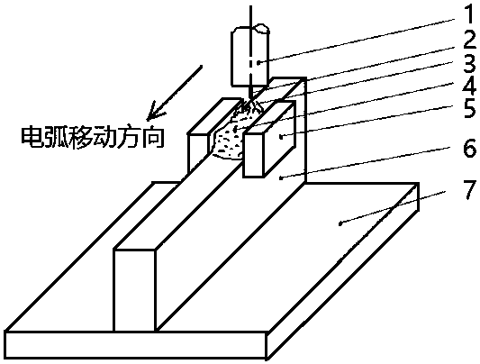
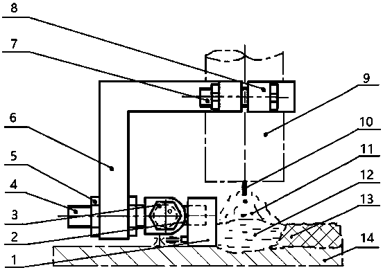
[0026] image 3 The assembly diagram of the one-sided forming device for the additive manufacturing of thick and large samples, the forming die (1) is installed on the connecting rod (2) through threaded connection, and the connecting rod (2) and the extension rod (4) are clamped by the bolt nut ( 3) Connect and fix, and use the nut (5) to clamp and install on the bracket (6), and the bracket (6) is fixed to the nozzle (9) of the welding torch by using the clamp (8) and the bolt and nut (7). Figure 4 This is an example of the mold shape and size used. Loosen the bolt and nut (7) to adjust the position of the fixture (8) and bracket (6) on the welding torch nozzle (9), thereby adjusting the distance from the nozzle to the surface of the workpiece during forming. Loosen the nut (5) to adjust the position of the extension rod (4) left and right, thereby adjusting the width of the weld bead. Loosen the nut (3) clamping the connecting rod (2) and the extension rod (4), so that t...

Embodiment 2

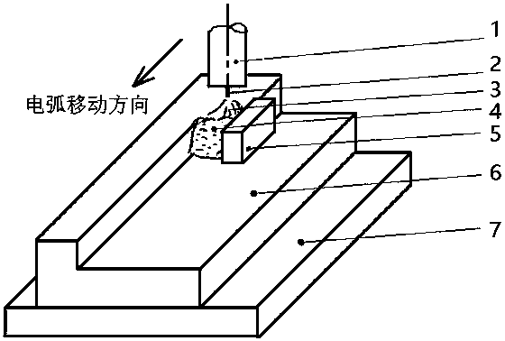
[0028] Figure 5The assembly diagram of the double-sided forming die device for the additive manufacturing of thin-walled samples, the forming dies and supports on both sides are symmetrical, the forming die (1) is installed on the connecting rod (2) through threaded connection, and the connecting rod (2) and the extension rod (4) Connect and fix by clamping bolts and nuts (3), and use the nuts (5) to clamp and install on the bracket (6), and the brackets (6) on both sides are fixed to the nozzle (8) of the welding torch by using the bolts and nuts (7) superior. The position of the bracket (6) on the welding torch nozzle (8) can be adjusted by loosening the bolt and nut (7), thereby adjusting the distance from the nozzle to the surface of the workpiece during forming. Loosen the nut (5) to adjust the position of the extension rod (4) left and right, thereby adjusting the width of the weld bead. Loosen the nut (3) clamping the connecting rod (2) and the extension rod (4), so ...

Embodiment 3

[0030] When the moving path of the arc is a circular arc, such as when forming thin-walled cylindrical parts, the mold fixture still uses Figure 5 As shown in the device, the forming die adopts Image 6 , Figure 7 As shown in the structure, the outer wall of the cylinder adopts Image 6 The mold shown, the inner wall of the cylinder adopts Figure 7 mold shown. Select according to the radius and wall thickness of the forming cylinder Image 6 and Figure 7 The arc radius r of the mold.


PUM


Abstract

The invention discloses a method for improving arc additive manufacturing precision and forming efficiency of a wire material and belongs to the technical field of advanced manufacturing. The problemsthat during arc additive manufacturing of a conventional wire material, the size precision and the surface quality of samples are poor, the heat inputting is limited, and the forming efficiency is not high are solved. According to the method, the relative positions of a forming mold and a welding gun are fixed, the mold forming face in the forming process is made to keep being in contact with theside face of a molten pool, the shape of the molten pool is restrained, the molten pool is made to be solidified under the mold restraint, micro casting of metal of the molten pool is achieved, and the consistency of the welding bead width and stable process parameters are guaranteed in the forming process, so that the size precision and the surface quality of the formed samples can be improved;and by means of water cooling on the mold, cooling on the molten pool is enhanced, changing of the cooling conditions is reduced, and the uniformity of the performance of the structures of the samplesis guaranteed. On the other hand, because the mold is adopted to restrain the metal of the molten pool, the linear energy can be increased, it is not needed to worry that because of free flowing of the molten pool, forming cannot be achieved, and therefore the forming efficiency is improved.

Description

technical field [0001] The invention belongs to the field of advanced manufacturing technology, and provides a method for improving the accuracy and forming efficiency of wire arc additive manufacturing, which is used for additive manufacturing of parts and molds, can improve the dimensional accuracy and surface quality of samples, and improve the forming efficiency. Background technique [0002] Wire Arc Additive Manufacturing (Wire Arc Additive Manufacturing, WAAM) uses arcs such as non-melting electrodes, melting electrodes or plasma arcs as heat sources, and is formed by continuously melting wire materials layer by layer. It has the advantages of large forming size, simple equipment, low cost, It has the advantages of high material utilization rate and deposition efficiency, and the cladding rate can reach 50~130g / min. It is a practical method for producing medium and large parts, and has become one of the methods that can realize economical and rapid prototyping of high-...

Claims


Application Information

Patent Timeline
IPC IPC(8): B23K9/04B23K9/32B23K37/06
CPCB23K9/042B23K9/32B23K37/003B23K37/06
Inventor 张元彬孙俊华史传伟王泽利王珂
Owner SHANDONG JIANZHU UNIV
Why Eureka
Try Eureka