Separating-connecting type safety anti-theft lock

A clutch-type, anti-theft lock technology, applied in the field of locks, can solve problems such as inability to provide security, achieve high anti-theft safety performance, improve life, and avoid damage and breakage

Active Publication Date: 2018-03-16
上海英特罗机械电气制造股份有限公司
6 Cites 0 Cited by

AI-Extracted Technical Summary

Problems solved by technology

The basic structure of the anti-theft locks currently on the market does not depart from the design framework of traditional mechanical locks. W...

Method used

[0040] When the present invention is in use, the knob shaft is rotated by turning the knob on one side of the knob, so that the lock is opened after driving the dead bolt shifting block to rotate. On the side of the lock cylinder, after the key is inserted into the lock cylinder, the conductor contact piece contacts the lock cylinder probe, the lock cylinder probe touches the left lock body probe, the lock body sealing piece, and the right lock body probe contacts the conductive ring, the conductive ring After connecting the motor drive circuit, the circuit path is established, and the signal of the control module is transmitted to the drive circuit to realize the drive of the motor. After realizing the coaxial connection between the lock cylinder and the deadbolt shift block, twist the key to turn the dead bol...

Abstract

The invention relates to the technical field of anti-theft locks, in particular to a separating-connecting type safety anti-theft lock. According to the separating-connecting type safety anti-theft lock, a lock body is internally provided with a lock tongue shifting block and a knob shaft for driving the lock tongue shifting block to rotate; the lock body comprises a shaft coupling device for shaft coupling of the knob shaft and a lock cylinder, the shaft coupling device comprises a motor located on the right side of the knob shaft, and a knob shaft connector which is in threaded connection with the knob shaft is arranged at the tail part of the stretching-out end of a rotating shaft of the motor in a sleeving mode; an open groove is formed in the outer wall of an opening of the left end of the knob shaft, and a protrusion for being conveniently clamped into the open groove is arranged on the outer wall of the knob shaft connector; and a lock cylinder connector which conveniently enables the lock cylinder and the knob shaft to conduct shaft coupling rotation is arranged on the right side of the lock cylinder, and the lock cylinder connector is connected with the right end of the lock cylinder through a spring. By adopting the technical scheme, the separating-connecting type safety anti-theft lock is novel in structure and reasonable in design, through the mode that the motor isarranged in a lock handle and a control signal generating circuit is arranged in a key, the effect that unlocking is conducted through the specific key is achieved, and security anti-theft performance of the lock is enhanced.

Application Domain

Technology Topic

Anti theftType safety +3

Image

  • Separating-connecting type safety anti-theft lock

Examples

  • Experimental program(1)

Example Embodiment

[0032] In order to make the technical means, creative features, goals and effects achieved by the present invention easy to understand, the present invention will be further described below in conjunction with specific diagrams.
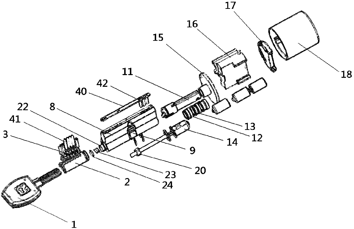
[0033] refer to figure 1 , Clutch-type security anti-theft lock, including a key 1 and a lock body 8, the lock body 8 is provided with a lock cylinder 2 and a deadbolt shift block 9, both of which are separate structures. The opening and closing of the lockset is realized after the dead bolt shifting block 9 is dialed forward or backward. The left side of deadbolt shifting block 9 is lock core 2, and the right side is provided with knob shaft 11, and knob shaft 11 and dead bolt shifting block 9 joint shafts rotate, and knob shaft 11 connects the knob handle that is positioned at the right side of lock body 8, twists The knob handle drives the deadbolt shifting block 9 to rotate through the knob shaft 11, so as to realize the effect of opening the lockset on the opposite side of the lock cylinder.
[0034] The lock cylinder 2 is provided with a lower pin storehouse which is convenient for the lower pins to move up and down, and the lower pins are placed therein. The lock body 8 is provided with an upper pin storey which is convenient for the upper pins to move up and down. The upper pin storey is located directly above the lower pin storehouse. There are upper marbles placed therein, and the upper marbles correspond to the lower marbles one by one.
[0035] It also includes a shaft coupling device for coaxial rotation after the dead bolt shift block 9 is connected with the lock cylinder 2. The shaft coupling device includes a motor 14, the motor 14 is located on the right side of the knob shaft 11, and the motor shaft extends into the left side. In the hollow cavity of the knob shaft 11 with openings at both ends, a knob shaft connector 20 threadedly connected with the motor shaft is sleeved at the end of the motor shaft extension. The outer wall of the connector 20 is provided with a protrusion which is convenient to be inserted into the slot. There are two card slots, which are arranged at the opposite position of the end face of the opening of the knob shaft 11, and the slotting direction is the left and right directions, so that the protrusions that are convenient to be inserted into it can move left and right along the slotting direction, correspondingly, snap into the There are also two protrusions of the card slot, which are located at opposite positions on the outer wall of the knob shaft connector 20 . After the motor 14 is powered on and receives the control signal, the motor shaft rotates counterclockwise, so that the knob shaft connector 20 rotates counterclockwise together. The rotation is restricted behind the card slot, so that it can only move in the axial direction, and its effect is to make it move towards the direction of the lock cylinder. The right side of the lock cylinder 2 is provided with a lock cylinder connector 22 which facilitates the joint rotation of the lock cylinder 2 and the deadbolt shifting block 9 . A left and right through chamber is arranged inside the deadbolt shifting block 9, and the lock cylinder connector 22 is placed in the chamber. The knob shaft 11 passes through the chamber of the deadbolt shifting block from right to left, and its left end opening is located on the right side of the lock cylinder connector 22 . The right end of the lock cylinder 2 is provided with a storage chamber opening to the right, in which a spring 23 with a telescopic direction as the left and right directions is provided, the right end of the spring 23 is located on the left side of the lock cylinder connector 22, and a spring seat is provided on the left side of the spring 23 24, for fixing spring 23. The lock cylinder connector 22 is placed in the chamber of the deadbolt shifting block 9. When the motor 14 works, the rotation of the motor shaft makes the knob shaft connector 20 move to the left, and pushes the lock cylinder connector 22 to move to the lock cylinder 2 together. , and finally push the lock cylinder connector 22 into the storage cavity of the lock cylinder 2 . In order to make the lock cylinder connector 22 realize the effect of coaxial rotation after the lock cylinder and the lock tongue shifting block are connected, the depth of the storage cavity of the lock cylinder can be set to be less than the length of the lock cylinder connector 22 in the left and right direction, so that the lock When the core connector 22 is pushed into the limit, a part is still located in the deadbolt shifting block 9, so that the lock core connector 22 can transmit the torque from the key 1, so that when the key 1 is twisted, it can drive the lock core 2, The lock cylinder connector 22 and the dead bolt shifting block 9 rotate together to realize the effect of opening the lockset on one side of the lock cylinder. In actual setting, the lock cylinder and the lock tongue shifting block should be as close as possible to enhance the connection effect of the lock cylinder connector. In order to achieve the connection effect of the lock cylinder connector 22, its shape is set to a straight column structure with a non-circular cross section, and the corresponding structure of the chamber of the deadbolt dial 9 and the storage cavity of the lock cylinder 2 is set to be consistent with that of the lock cylinder 22. The shape-matching structure of the lock cylinder connector 22 makes it convenient for the lock cylinder connector 22 to extend into the chamber of the deadbolt shifting block 9 and the storage chamber of the lock cylinder 2, and also facilitates the force of twisting the key 1 to be effective successively. Conducted to the lock cylinder 2, the lock cylinder connector 22 and the deadbolt shifting block 9. In actual setting, the shape of the lock cylinder connector can be set as a straight column structure with a polygonal cross section, preferably an upright column with a triangular, quadrilateral, pentagonal or hexagonal cross section.
[0036] The key 1 is equipped with a control module for sending motor drive signals to the shaft coupling, which is connected to the drive circuit of the motor 14 through an electrical connection component, so as to achieve the effect of sending control signals to the shaft coupling after inserting the key 1 into the lock cylinder 2 . The electrical connection assembly includes the conductor contact piece in the key shaft of the key 1, the lock cylinder probe 3 in the lock cylinder 2, the left lock body probe 41 and the right lock body probe 42 in the lock body 8, the upper end surface of the lock body 8 The conductive ring 13 on the lock body sealing piece 40, the knob shaft 11, each component of the electrical connection assembly is made of a conductor, the conductive ring 13 is a ring structure, and it is connected to the driving circuit of the motor 14, and the left lock body probe 41 Located directly above the lock cylinder probe 3 and contacting the lock cylinder probe 3 downwards to form an electrical connection, the right lock body probe 42 is located directly above the conductive ring 13 and contacts the outer wall of the conductive ring 13 downwards to form an electrical connection, After the key 1 is inserted into the lock cylinder 2, the conductor contact piece contacts the lock cylinder probe 3 to form an electrical connection. The left lock body probe 41 and the right lock body probe 42 both expose the upper end surface of the lock body and cover the upper end surface of the lock body. The lock body sealing sheet 40 is connected, the lock body sealing sheet 40 lower surface is provided with the circuit for connecting the left lock body probe 41 and the right lock body probe 42, and the conductor contact piece is connected to the control module in the key. The right lock body probe 42 is connected to the lock body sealing piece 40 by a reed whose telescoping direction is the up and down direction, so that when the lock body sealing piece 40 covers the upper end surface of the lock body, the reed is compressed, and the reed is compressed by the restoring force of the reed The right lock body probe 42 is pressed against the outer wall of the conductive ring 13 on the knob shaft 11 .
[0037] The drive circuit of the motor 14 is provided with at least two input terminals, any input terminal is connected to a conductive ring 13, and an insulating ring 12 for electrical isolation is provided between adjacent conductive rings 13, and the insulating ring 12 is sheathed and fixed on the knob The outer wall of the shaft 11. The conductive ring 13, the right lock body probe 42, the left lock body probe 41, and the lock core probe 3 are one-to-one correspondence structures, corresponding to any left lock body probe 41, and corresponding The independent circuit is used to connect the right lock body probe 42 corresponding thereto, and the conductor contact piece on the key shaft is in one-to-one correspondence with the lock core probe 3 .
[0038] The knob includes a knob seat 16 and a knob seat housing 18 with a cover outside the knob seat. The knob seat 16 is provided with a motor compartment for placing and fixing the motor 14 and a control compartment for placing and fixing the motor drive circuit. The power supply compartment is used to place and fix the built-in power supply of the motor, and the power supply compartment is connected with the driving circuit of the motor. The built-in power supply of the motor adopts dry batteries. The left and right ends of the knob seat 16 are respectively provided with a knob seat upper cover 15 and a knob seat bottom cover 17. The knob seat shell 18 is a ring-shaped shell that is closed after a circle around the knob seat 16. The knob seat 16 is covered by the knob seat shell 18, the knob Seat loam cake 15 and knob seat bottom cover 17 are closed, and knob seat loam cake 15 is provided with the through hole that stretches into knob shaft 11 after being convenient to motor rotating shaft to stretch out to the left.
[0039] The key shaft is provided with a chute, which is used to place and fix the conductor contact piece, and the control module is placed and fixed in the key shaft, and the key shaft is provided with a drive circuit for the control module and the motor to the motor 14 External signal input interface for power transmission, the external signal input interface is connected to the control module, so that when the internal power supply of the motor 14 is short of power, the lock can be opened by external power supply. Preferably, the external signal input interface adopts a USB interface.
[0040] When the present invention is in use, the knob shaft is driven to rotate by turning the knob on one side of the knob, so that the lock is opened after the lock tongue shifting block is driven to rotate. On the side of the lock cylinder, after the key is inserted into the lock cylinder, the conductor contact piece contacts the lock cylinder probe, the lock cylinder probe touches the left lock body probe, the lock body sealing piece, and the right lock body probe contacts the conductive ring, the conductive ring After connecting the motor drive circuit, the circuit path is established, and the signal of the control module is transmitted to the drive circuit to realize the drive of the motor. After realizing the coaxial connection between the lock cylinder and the deadbolt shift block, twist the key to turn the dead bolt shift block to open the lock. ; After the key is removed, the unlocking signal is lost, so the motor drive circuit controls the motor to rotate in reverse to separate the lock cylinder and the bolt shifting block. At this time, even if the key's teeth are correct, the lock cannot be opened, which improves the safety performance of the product . The design of the conductive ring solves the shortcomings of the traditional structure of the line damage caused by the rotation of the knob shaft, so that the product has a better service life and stable performance.
[0041] In order to make the present invention easy to use, a buzzer and a signal indicator light for indicating the working state are set on the key, and the daily use of the lock is realized through the following management methods, which include the configuration of the function type of the key and the number of times of use Restrictions, the key includes three types, namely management card key, user card key and temporary card key; the management card key is used to add or delete the login information of the user card key and temporary card key, which does not have the function of opening the lock; The card key is used for the normal opening of the lock, and it does not set a limit on the number of times of use; the temporary card key is used for the temporary opening of the lock, and it is set to a limit on the number of times of use, preferably set to 1 time, and it will be invalid after 1 use.
[0042] The drive circuit of the motor is provided with a key management module for configuring and managing three types of keys, and the present invention realizes the type distribution and management of keys through the keys and the key management module.
[0043] Only one management card key is set, 3 to 50 user card keys are set, and 1 to 6 temporary card keys are set.
[0044] The basic principles and main features of the present invention and the advantages of the present invention have been shown and described above. Those skilled in the industry should understand that the present invention is not limited by the above-mentioned embodiments. What are described in the above-mentioned embodiments and the description only illustrate the principle of the present invention. Without departing from the spirit and scope of the present invention, the present invention will also have Variations and improvements are possible, which fall within the scope of the claimed invention. The protection scope of the present invention is defined by the appended claims and their equivalents.

PUM

no PUM

Description & Claims & Application Information

We can also present the details of the Description, Claims and Application information to help users get a comprehensive understanding of the technical details of the patent, such as background art, summary of invention, brief description of drawings, description of embodiments, and other original content. On the other hand, users can also determine the specific scope of protection of the technology through the list of claims; as well as understand the changes in the life cycle of the technology with the presentation of the patent timeline. Login to view more.

Similar technology patents

Lost foam casting process

Owner:HANZHONG YANHANG PRECISION MACHINERY MFG

Classification and recommendation of technical efficacy words

  • Not easy to crack
  • Improve anti-theft security performance

Raw material formula of bronzy sculpture

ActiveCN104446286AGood viscosityNot easy to crackParaffin waxRosin
Owner:厦门鼎艺雕塑有限公司

2Cr11MoVNbN forge piece for steam turbine and manufacturing method of forge piece

ActiveCN106282836ANot easy to crackHigh temperature durabilityEngineeringStress relief
Owner:ZHANGJIAGANG HAILU ANNULAR FORGINGS

Flexible tile adhesive

InactiveCN105645860AStrong bonding abilityNot easy to crackEtherAdhesive
Owner:SHUN TAN SHANGHAI NEW MATERIALS CO LTD

Electromagnetic control lock for cabinet

InactiveCN110670974APrevent unlockingImprove anti-theft security performanceNon-mechanical controlsClutchCam
Owner:FUYANG WANRUI ELECTRONICS LOCKS CO LTD

Security antitheft lock and unlocking and locking method

ActiveCN106481160AImprove anti-theft security performanceImprove usabilityPadlocksMechanical engineering
Owner:JIANGSU HONGPU TECH LTD
Why Eureka
Try Eureka