Compressive sensing imaging device and method

An imaging device and compressed sensing technology, which is applied in the direction of measuring devices, optical device exploration, and material analysis through optical means, can solve the problems of imaging distance and imaging quality degradation, low image reconstruction accuracy, etc., to improve accuracy, Avoid the effects of influence

Pending Publication Date: 2018-03-16
苏州蛟视智能科技有限公司
View PDF8 Cites 0 Cited by
  • Summary
  • Abstract
  • Description
  • Claims
  • Application Information

AI Technical Summary

Problems solved by technology

[0006] The present invention provides a compressed sensing imaging device and method to solve the problems of low image reconstruction accuracy, reduced imaging distance and imaging quality due to the influence of PSF in bad weather conditions or in water in the prior art

Method used


Image

  • Compressive sensing imaging device and method
  • Compressive sensing imaging device and method
  • Compressive sensing imaging device and method

Examples


Embodiment 1

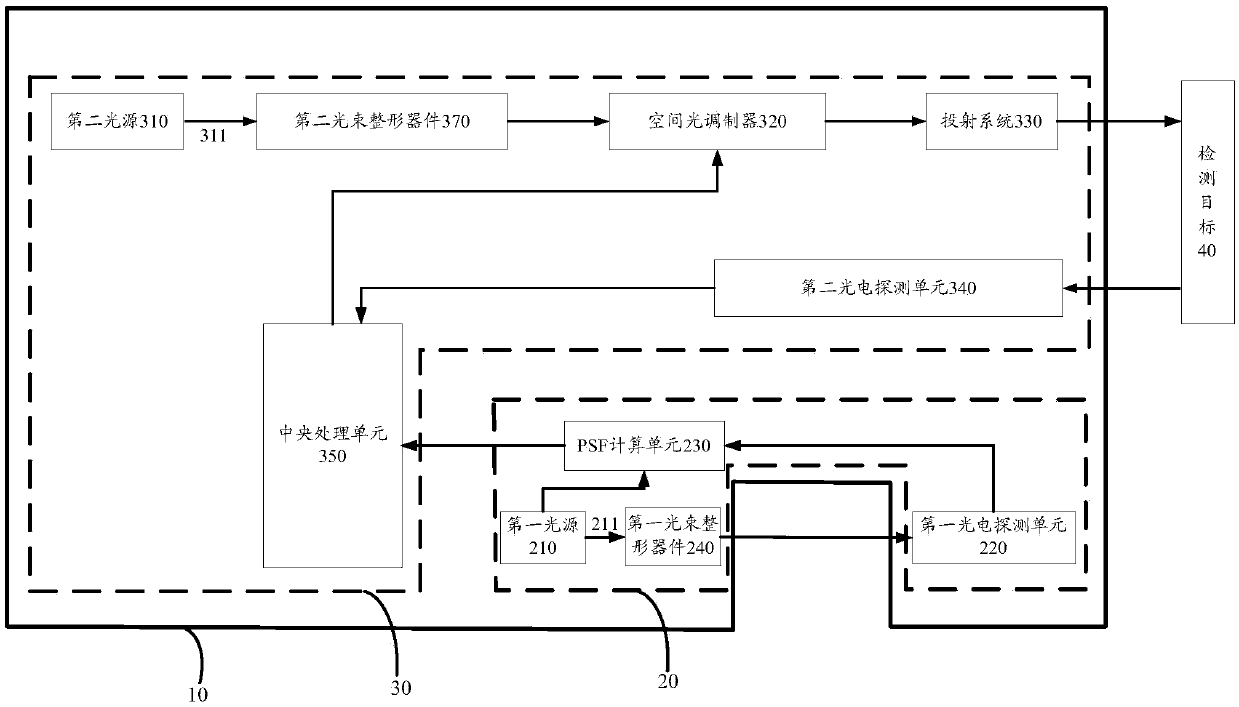
[0050] like Figure 2-3 As shown, the present invention provides a compressive sensing imaging device, including: a carrier 10 and a PSF measurement system 20 and an imaging system 30 located on the carrier.

[0051] The PSF measurement system 20 includes a first light source 210, a first photodetection unit 220 and a PSF calculation unit 230, the first photodetection unit 220 is connected to the PSF calculation unit 230, and the first light source 210 emits A light beam 211 enters the first photoelectric detection unit 220 after passing through the air / water body, the first light source 210 and the first photoelectric detection unit 220 are connected to the PSF calculation unit 230, and the divergence angle of the first light beam 211 is less than 5 mrad, That is to ensure that the first light beam 211 has better collimation and form a point spot as small as possible so that it can be better detected by the first photodetection unit 220 and improve the measurement accuracy of...

Embodiment 2

[0072] Different from Example 1, the imaging method provided in this example includes the following steps:

[0073] S1: measure the distance r that the first light beam 211 needs to travel in the air / water body and the distance R that the second light beam 311 needs to travel in the air / water body when it is projected on the detection target 40; since the PSF value measured by the PSF measurement system 20 is For the value under the distance r, however, since the distance R traveled in the air / water body when the second light beam 311 is projected onto the detection target 40 is different from the distance r, it is necessary to perform a conversion according to the distance between the two to obtain the corresponding The PSF value. Similarly, measuring the PSF in this embodiment mainly refers to measuring the spectrum value MTF of the PSF. To convert it into a PSF value, it is only necessary to perform an inverse Fourier transform on the MTF.

[0074] S2: Turn on the first li...

Embodiment 3

[0080] like Image 6 As shown, the difference from Embodiment 1 is that in this embodiment, the second light source 310 is a wide-spectrum light source, and a wavelength selection unit 360 is also provided behind the wide-spectrum light source along the optical path. The light beam includes a plurality of monochromatic lights with different wavelength bands, the first light source 210 includes a plurality of monochromatic light sources with different wavelength bands that correspond one-to-one to the monochromatic lights with different wavelength bands, the wavelength selection unit 360 and the The plurality of monochromatic light sources with different wavelength bands are all connected to the central processing unit 350 , and the first photodetection unit 220 respectively receives the light emitted by the plurality of monochromatic light sources with different wavelength bands. Specifically, in this embodiment, the wide-spectrum light source adopts a color-mixing light sourc...


PUM


Abstract

The invention discloses a compressive sensing imaging device and a compressive sensing imaging method. The compressive sensing imaging device comprises a carrier, a PSF (Point Spread Function) measuring system and an imaging system, wherein the PSF measuring system and the imaging system are arranged on the carrier. Due to adoption of the PSF measuring system, a first light beam emitted from a first light source passes through air / a water body and is received by a first photoelectric detection unit, then energy distribution information of a light spot affected by a PSF is received, a frequencyspectrum value of the PSF of the air / water body in a specific distance is calculated by a PSF calculation unit according to energy distribution of the light spots emitted from the first light sourceand energy distribution information of light spot imaging detected by the first photoelectric detection unit, a frequency spectrum value of the PSF of the air / water body corresponding to an imaging unit is calculated through a central processing unit, a micro lens in a spatial light modulator is adjusted according to the frequency spectrum value, then light intensity distribution to a detection target from the micro lens is identical to an original modulation matrix, and thus the influence of the PSF is inhibited.

Description

technical field [0001] The invention relates to the field of target detection, recognition and imaging, and in particular to a compressed sensing imaging device and method. Background technique [0002] Correlated imaging, also known as ghost imaging, is a quantum or classical correlation characteristic based on light field fluctuations. Through the intensity correlation operation between the reference light field and the target detection light field, the non-definite A new imaging technology that obtains target image information locally. However, traditional correlative imaging has the problems of large sampling times, long imaging time, and complex system structure, and is not suitable for imaging in complex and changeable environments. Compressive Sensing technology is a new signal sampling technology that has emerged in recent years. Different from the traditional Nyquist sampling theorem, this technology synchronizes the signal compression process with the sampling pro...

Claims


Application Information

Patent Timeline
IPC IPC(8): G01N21/01G01V8/10
CPCG01N21/01G01V8/10
Inventor 黄帆韩捷飞初宁蔡栋龙涛邹诚
Owner 苏州蛟视智能科技有限公司
Why Eureka
Try Eureka