
Hydrate phase change process visualization CT (computer tomography) device based on high pressure throttling temperature control technology

A high-pressure throttling and hydrate technology, applied in the field of hydrate basic research, can solve the problems of difficult measurement and realization of decomposition surface area

Active Publication Date: 2018-03-16
DALIAN UNIV OF TECH
View PDF5 Cites 9 Cited by
  • Summary
  • Abstract
  • Description
  • Claims
  • Application Information

AI Technical Summary

Problems solved by technology

[0005] in, is the molar rate of hydrate decomposition, k d is the reaction kinetic constant, f e is the fugacity of gas, water and hydrate three-phase equilibrium, f g is the local fugacity, A s is the hydrate decomposition surface area, because it is difficult to realize the microscopic visualization in the pores, and it is difficult to measure the hydrate decomposition surface area in the porous medium. At present, there is no suitable model for the decomposition surface area. Natural gas hydrate formation and decomposition process to obtain the calculation formula of hydrate decomposition surface area

Method used


Image

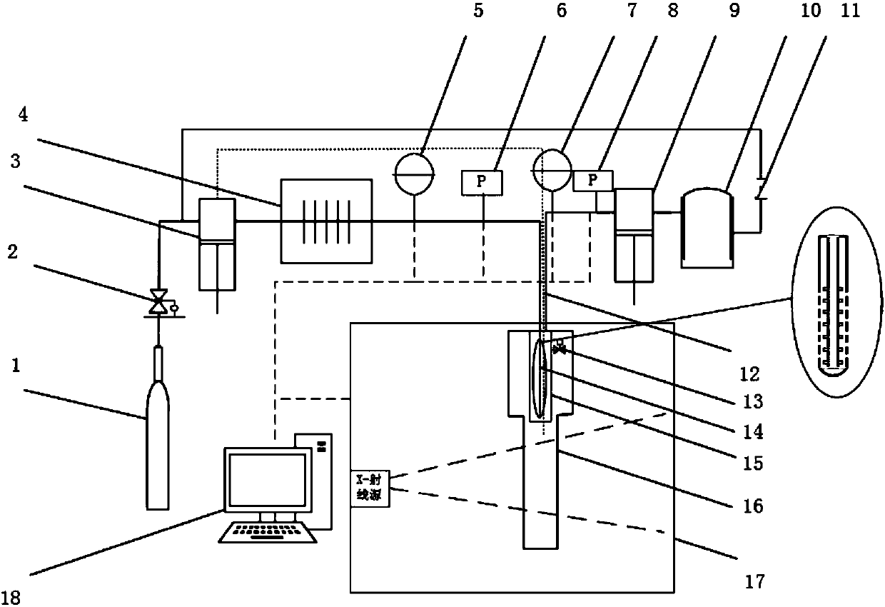
  • Hydrate phase change process visualization CT (computer tomography) device based on high pressure throttling temperature control technology
  • Hydrate phase change process visualization CT (computer tomography) device based on high pressure throttling temperature control technology

Examples


Embodiment Construction

[0020] The specific embodiments of the present invention will be described in detail below in conjunction with the technical solution and the drawings.

[0021] figure 1 Shown is the schematic diagram of the X-ray CT device structure for studying the fractal theory of natural gas hydrate formation and decomposition process.

[0022] (1) The preparation process is: take out the temperature control tank 15, open the self-operated pressure regulating valve 13, inject a certain amount of water into the reaction tank 16, then put the temperature control tank 15 into the reaction tank 16, and connect the experimental device . Turn on the X-ray CT scanning device to scan.

[0023] (2) The gas injection process is: open the pressure regulating valve 2, open the first air pump 3, make the first air pump 3 constant pressure (high pressure) injection, the initial gas injection process, the first temperature sensor 5, the second temperature sensor 7, The first pressure gauge 6 and the second ...


PUM


Abstract

The invention provides a hydrate phase change process visualization CT (computer tomography) device based on a high pressure throttling temperature control technology, which belongs to the technical field of basic research on hydrates. High pressure gas enters a temperature control pool through a gas pump and a low temperature probe; the high pressure gas can be used for realizing temperature control through throttling expansion heat absorption of the low temperature probe; the temperature control pool is connected with a reaction pool by a self-operated pressure regulating valve; the pressurein the reaction pool can be controlled by the self-operated pressure regulating valve, so that the generation and decomposition of methane hydrate can be controlled. An outlet gas pump is connected with the temperature control pool, so as to control the pressure in the temperature control pool. The generation and decomposition process of the methane hydrate is scanned by X-ray CT timely. A high pressure gas throttling low temperature device is combined with the X-ray CT, so that the temperature can be controlled by throttling expansion of high pressure methane, and the problem that the temperature is relatively difficult to control as a reaction kettle rotates in the X-ray CT scanning process is solved. A three-dimensional structure of the generation and decomposition process of the methane hydrate on the surface of a porous medium can be visually observed through combination with the X-ray CT scanning, so as to provide basic data for a research on numerical simulation of generation and decomposition of the hydrate.

Description

Technical field [0001] The invention belongs to the technical field of hydrate basic research, and relates to a visual CT device for a hydrate phase change process based on a high-pressure throttling and temperature control technology. Background technique [0002] The resource crisis is one of the three major problems facing the world today. Natural gas hydrates have attracted attention due to their relatively clean, high energy density and large reserves. One cubic meter of natural gas hydrate can release 164 cubic meters of natural gas. The U.S. Geological Survey pointed out that the potential carbon content of natural gas hydrates is about twice that of conventional fossil energy available in the world. Therefore, how to efficiently exploit natural gas hydrate reservoirs has been studied by many countries. [0003] At present, there have been great breakthroughs in the research on the decomposition kinetics of natural gas hydrate, and the decomposition kinetic model has been ...

Claims


Application Information

Patent Timeline
IPC IPC(8): G01N23/044
CPCG01N23/046
Inventor 宋永臣高祎杨明军赵越超刘卫国刘瑜
Owner DALIAN UNIV OF TECH
Learn More