

Marine exhaust gas washing device
A technology for ship exhaust and scrubbing devices, which is applied in the separation of dispersed particles, chemical instruments and methods, and the use of liquid separators, etc., can solve the problem of not using the main and secondary scrubbing sections for stepped scrubbing and other problems.
- Summary
- Abstract
- Description
- Claims
- Application Information
AI Technical Summary
Problems solved by technology
Method used
Image

Examples
Embodiment 1
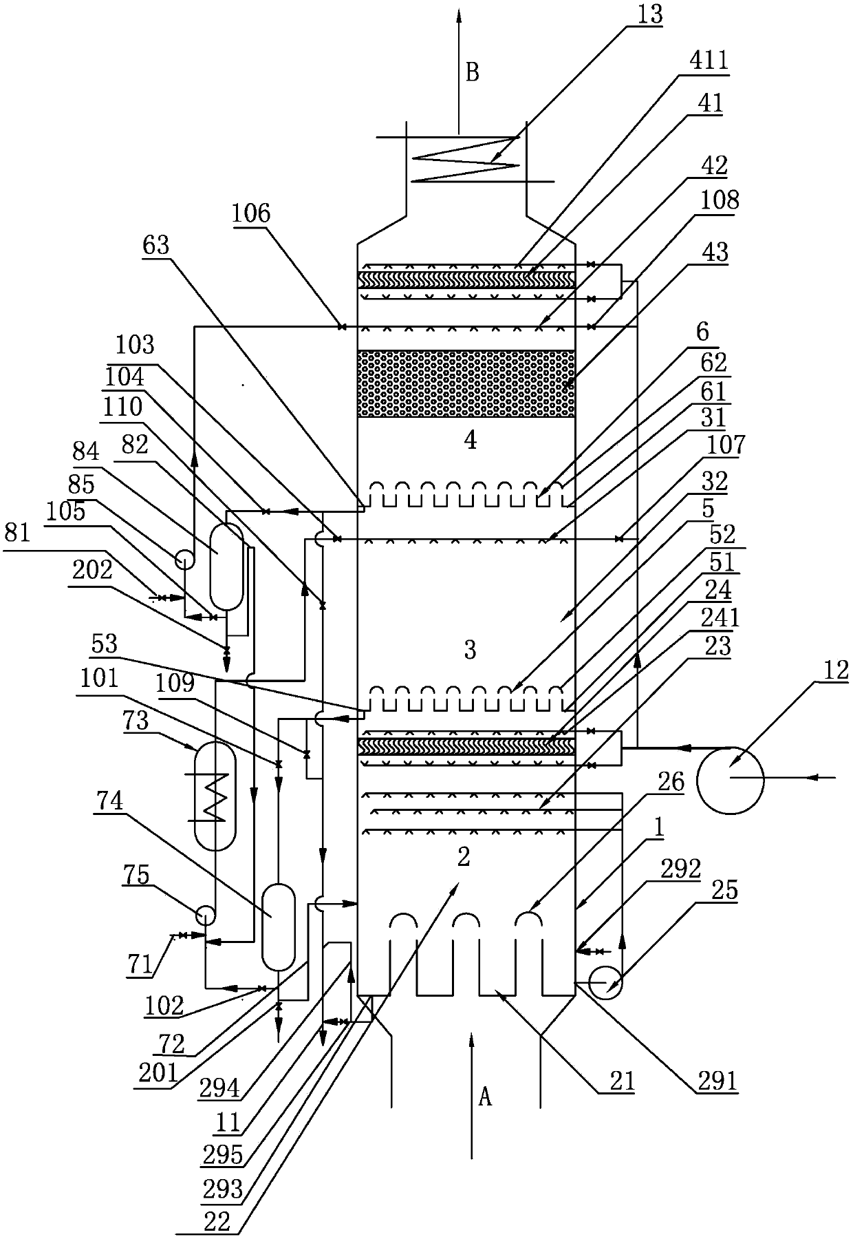
[0036] A kind of ship tail gas scrubbing device that present embodiment proposes, such asfigure 1 As shown, it includes a washing tower body 1, and the washing tower body 1 is provided with a ship exhaust gas inlet A, an evaporative cooling zone 2, a first washing zone 3, a second washing zone 4 and a ship exhaust gas outlet B from bottom to top, The exhaust air inlet A of the ship communicates with the evaporative cooling zone 2, and a first ventilation liquid blocker 5 that allows gas to circulate and prevents liquid circulation is provided between the evaporative cooling zone 2 and the first washing zone 3, and the first washing zone 3 and the first washing zone Between the second washing area 4, there is a second ventilation liquid blocker 6 that allows gas to circulate and prevents liquid from flowing. The second washing area 4 communicates with the exhaust port B of the ship. The evaporative cooling area 2 is equipped with an independent cooling liquid circulation. system...
Embodiment 2
[0047] A kind of ship tail gas scrubbing device proposed in this embodiment is as follows: figure 2 As shown, its structure is basically the same as that of the ship exhaust gas scrubbing device of Embodiment 1, the difference is that:
[0048]In this embodiment, the structure of the first lye circulation system is adjusted, specifically: the first lye circulation system includes the first liquid storage tank 35 arranged in the first washing area 3 and the first liquid storage tank 35 arranged in the washing tower body 1 outside the first circulation pump 75, the first liquid storage tank 35 is located below the first spray area 32, the bottom of the first liquid storage tank 35 is the first bottom plate 51, and the first liquid port 53 is connected in series with The pipeline of the first valve 101 is communicated with the inlet of the first circulation pump 75, and the inlet of the first circulation pump 75 is communicated with the outlet of the second overflow pipeline 82,...
Embodiment 3
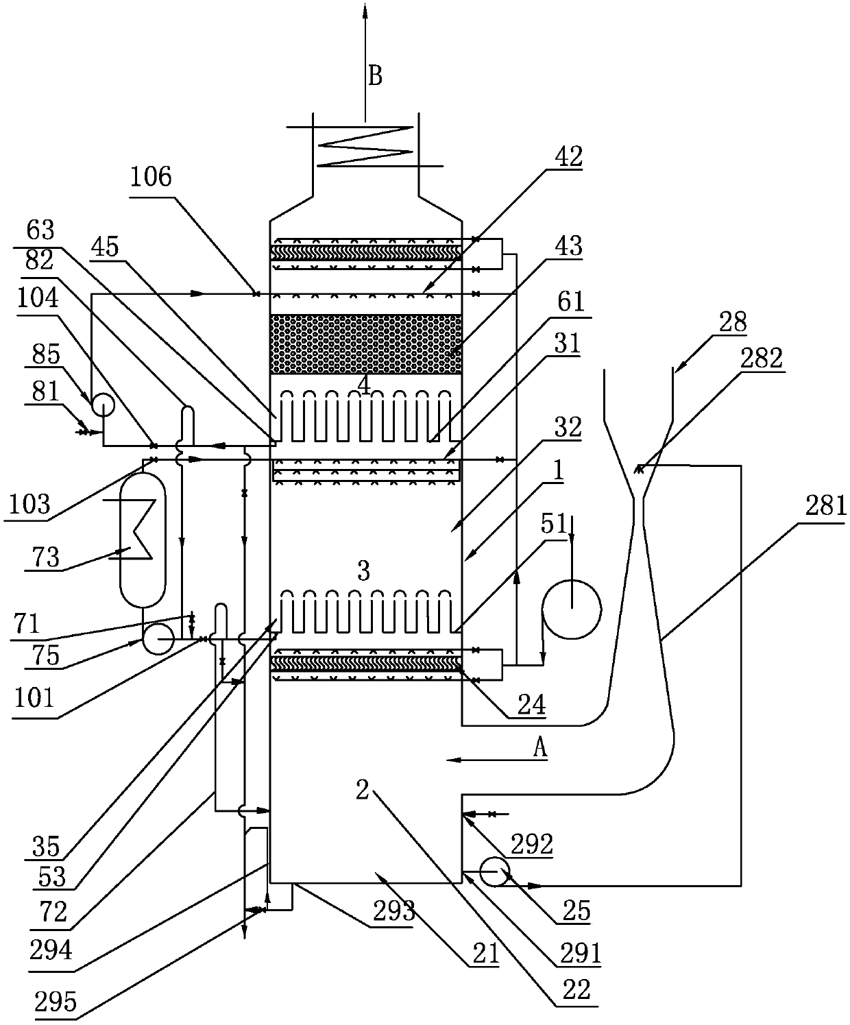
[0053] A kind of ship tail gas scrubbing device proposed in this embodiment is as follows: image 3 As shown, its structure is basically the same as that of the ship exhaust gas scrubbing device of Embodiment 1, the difference is that:
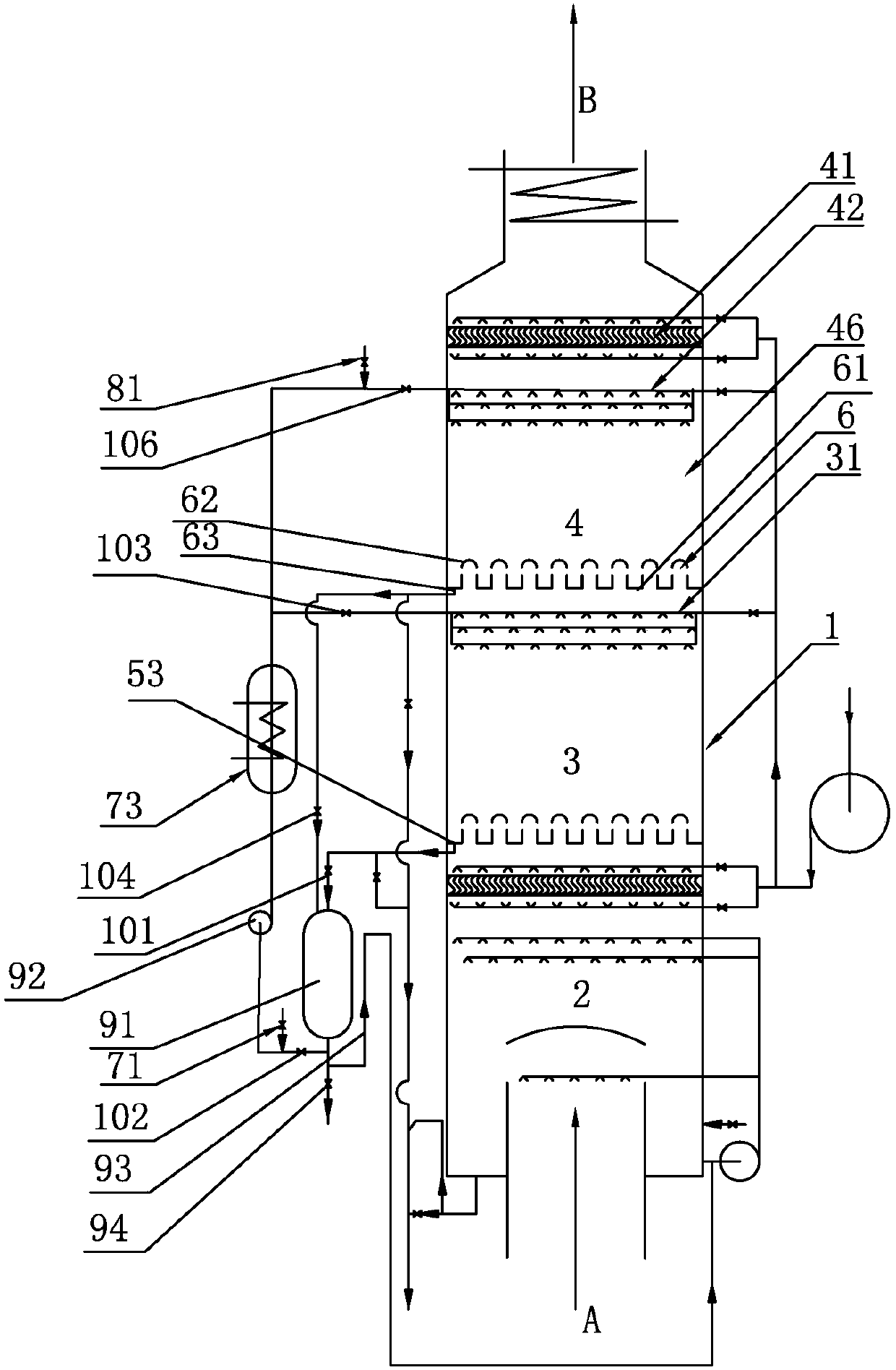
[0054] In this embodiment, the second washing area 4 adopts a spray empty tower structure, and its structure is composed of a second demister 41, a second washing liquid nozzle 42 and a second spraying area 46, and the second demister 41 is located at The top of the second washing liquid nozzle 42, the second washing liquid nozzle 42 is located above the second spray area 46, and the second ventilation liquid blocker 6 is located below the second spray area 46; the second air flow liquid blocker 6 adopts Wind cap structure, which includes a second bottom plate 61 and a second wind cap 62 installed on the second bottom plate 61, the second bottom plate 61 is provided with a second liquid port 63, and the second liquid port 63 is arranged on the...
PUM
 Abstract
Description
Claims
Application Information