Numerical control hydraulic transmission system

A hydraulic transmission and numerical control technology, which is applied to metal processing machinery parts, maintenance and safety accessories, metal processing equipment, etc., can solve the problems of wasting workshop space and energy, and achieve the effect of fast and accurate stop and saving workshop space

Inactive Publication Date: 2018-03-20
丹阳市协昌合金有限公司
View PDF7 Cites 0 Cited by
  • Summary
  • Abstract
  • Description
  • Claims
  • Application Information

AI Technical Summary

Problems solved by technology

This not only wastes energy but also wastes the customer's limited plant space

Method used


Image

  • Numerical control hydraulic transmission system

Examples


Embodiment Construction

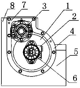
[0008] Depend on figure 1 It is known that a programmable hydraulic transmission system consists of a large gear 1, a high-sensitivity hydraulic motor 2, a servo encoder 3, a pinion 4, a screw 5, a screw slide 6, a mounting seat 7 and a dust cover 8 , the high-sensitivity hydraulic motor 2 is connected through the large gear 1, the pinion 4 and the screw 5, the high-sensitivity hydraulic motor 2 drives the large gear 1 to rotate, the pinion 4 and the screw 5 rotate accordingly, and the screw 5 is installed with a screw The slider 6 moves back and forth along the screw rod 5, the screw slider 6 is connected with a cutting tool, the screw rod 5 is movably connected to the mounting seat 7, the servo encoder 3 is installed on the tail of the screw rod 5 and the mounting seat 7, The screw 5 rotates, and the screw slider 6 moves on it. The servo encoder 3 measures the displacement according to the rotation of the screw 5. When the displacement set by the machine tool control system ...


PUM


Abstract

A numerical control hydraulic transmission system comprises a main gear, a high sensitivity hydraulic motor, a servo coder, a pinion, a lead screw, a spiral sliding block and a mounting seat. The highsensitivity hydraulic motor is connected to the lead screw by the main gear and the pinion, the high sensitivity hydraulic motor drives the main gear to rotate, the pinion and the lead screw follow to rotate, the lead screw is provided with the spiral sliding block and moves front and back along the lead screw, the spiral sliding block is connected to a cutting tool thereon, the lead screw is movably connected on the mounting seat, the numerical control hydraulic transmission system is characterized in that the outer edge of the lead screw is further provided with a dustproof cover for protecting the transmission lead screw, and the servo coder is mounted on the tail of the lead screw and the mounting seat. The numerical control hydraulic transmission system realizes programmable control,and can change a program in shorter time to meet the processing requirements of various products. A transmission torque is improved while the size of the device is not increased, a valuable workshopspace is saved for customers, and the numerical control hydraulic transmission system can be rapidly stopped precisely when needing to move at large speed.

Description

technical field [0001] The invention belongs to the technical field of special machine tools for mechanical processing, in particular to numerical control hydraulic transmission systems for chip cutting machine tools or conveying and transmission mechanisms that require large transmission torque and high displacement precision. Background technique [0002] With the continuous development of the current society, customers' demand for product replacement cycles is constantly accelerating; the machining accuracy of workpieces is also continuously improving; current enterprises are gradually improving the integration of products, and the functions of single products have increased. At the same time, some workpieces The volume of the machine will also increase, and the processing capacity of the machine tool will also increase. This has brought great trouble to some common processing industries. Most of the traditional processing in the past can satisfy a single mass production...

Claims


Application Information

Patent Timeline
Patent Type & Authority Applications(China)
IPC IPC(8): B23Q5/26B23Q11/08
CPCB23Q5/26B23Q11/08
Inventor 庄国祥
Owner 丹阳市协昌合金有限公司
Why Eureka
Try Eureka