
Cutting device

A technology for cutting devices and cutting tools, which is applied to fine working devices, electrical components, working accessories, etc., and can solve problems such as optical sensor pollution and false detection

Active Publication Date: 2018-03-20
DISCO CORP
View PDF7 Cites 0 Cited by
  • Summary
  • Abstract
  • Description
  • Claims
  • Application Information

AI Technical Summary

Problems solved by technology

[0010] However, in the mechanism disclosed in Patent Document 2, when a large amount of cutting chips is contained in the gas in the processing chamber, there is still a small gap in which the opening and closing cover remains, which may cause contamination of the optical sensor and cause erroneous detection. possibility of

Method used


Image

  • Cutting device
  • Cutting device
  • Cutting device

Examples


Embodiment Construction

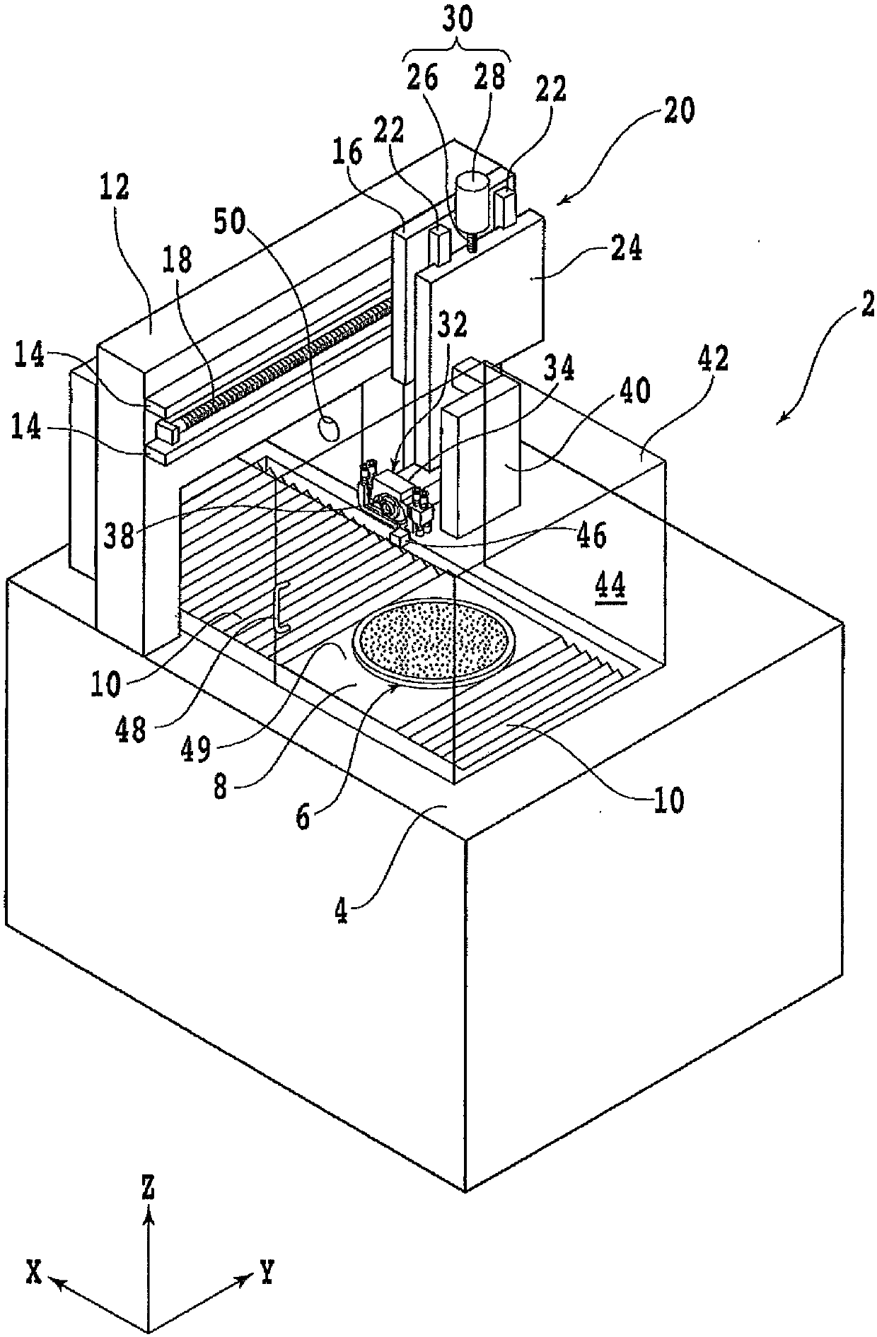
[0025] Hereinafter, embodiments of the present invention will be described in detail with reference to the drawings. refer to figure 1 , is a perspective view of a cutting device 2 having a non-contact setting mechanism (tool end detection mechanism) according to an embodiment of the present invention.

[0026] 4 is a base of the cutting device 2, and the chuck table 6 is arranged on the base 4, and the chuck table 6 is rotatable and can reciprocate in the X-axis direction by a machining feed member not shown. A waterproof cover 8 is disposed around the chuck table 6 , and a bellows 10 for protecting the shaft of the machining feed mechanism is connected between the waterproof cover 8 and the base 4 .

[0027] A door-shaped post 12 is erected behind the base 4 . A pair of guide rails 14 extending in the Y-axis direction are fixed to the column 12 . A Y-axis moving block 16 is mounted on the column 12, and the Y-axis moving block 16 can move along the guide rail 14 by a Y-ax...


PUM


Abstract

Provided is a cutting device with a non-contact setting mechanism. The cutting device comprises a chuck workbench for maintaining a machined object; a cutting unit for cutting the machined object by employing a cutting tool; a detection element for detecting the front position of the cutting tool; and a control element for controlling the chuck workbench, the cutting unit and the detection element. The detection element comprises a tool invasion portion; a light-emitting portion arranged at one side of the tool invasion portion; a light-receiving portion arranged at the other side of the toolinvasion portion and used for receiving light from the light-emitting portion; cleaning water nozzles used for supplying cleaning water for end surfaces of the light-emitting portion and the light-receiving portion and preventing attachment of cutting chips to the end surfaces; and air supply nozzles used for supplying air to the end surfaces. When the control element detects detection motion of the front position of the cutting tool, supply of the cleaning water and the air from the cleaning water supply nozzles and the air supply nozzles is stopped; and during standby except the detection motion, the cleaning water and the air are intermittently supplied to the end surfaces for removing the cutting chips attached on the end surfaces.

Description

technical field [0001] The present invention relates to a cutting device, and more particularly, to a cutting device capable of preventing contamination of the optical sensor while suppressing supply of washing water to an optical sensor of a non-contact installation mechanism. Background technique [0002] Various electronic components requiring precise cutting such as semiconductor wafers, ceramics, and glass are divided into individual chips by using a cutting device called a dicing machine. In the processing of these electronic components, precise dicing in the order of microns is required, and not only the size of the chip but also the depth of incision is important for this dicing. [0003] For example, the semiconductor wafer is fixed on the dicing tape, and the cutting tool is cut into the dicing tape by about 10 to 30 μm to completely cut the semiconductor wafer. However, if the cutting amount for the dicing tape is insufficient, the wafer cannot be completely cut. ...

Claims


Application Information

Patent Timeline
IPC IPC(8): B28D7/04B28D7/00B28D7/02B08B3/02B08B5/02
CPCB08B3/02B08B5/02B28D5/0058B28D5/0076B28D5/0082B28D7/00B28D7/02B28D7/04Y02P70/10H01L21/67092H01L21/67259H01L21/67051B28D5/0041B28D5/0023
Inventor 笠井刚史
Owner DISCO CORP
Features
  • Generate Ideas
  • Intellectual Property
  • Life Sciences
  • Materials
  • Tech Scout
  • Unparalleled Data Quality
  • Higher Quality Content
  • 60% Fewer Hallucinations
Learn More