A uniform coating device and method for optical fiber cylinder side

A coating device and optical fiber technology, which is applied in sputtering coating, vacuum evaporation coating, ion implantation coating, etc., can solve the problem of poor uniformity of film thickness in the arc direction of optical fiber, which affects the performance and volume of optical fiber reflection, polarization, etc. Large-scale and other problems, to achieve the effect of mass production, easy mass production, and small device volume

Active Publication Date: 2019-11-12
NANJING UNIV OF POSTS & TELECOMM
View PDF4 Cites 0 Cited by
  • Summary
  • Abstract
  • Description
  • Claims
  • Application Information

AI Technical Summary

Problems solved by technology

The disadvantage of this method is that the uniformity of the film thickness in the arc direction of the fiber is not good. This uneven film thickness will seriously affect the performance of the fiber reflection, polarization, etc., and even the surface plasmon resonance effect cannot be excited.
Chinese patent application CN 2898012Y discloses a rotary fixture that can be used for coating on the arc surface of an optical fiber. The disadvantage of this device is that the device is expensive, a synchronous motor needs to be specially customized, and the volume is relatively large, while the chamber of a general coating device is relatively large. Small (the diameter of the coating disk of the magnetron sputtering instrument is Ф125±2mm, the effective coating diameter is Ф75±2mm, and the chamber height is 50±2mm); in addition, the entire rotating fixture has no outer frame closure structure, which will seriously affect the environment of the coating chamber. This will affect the coating quality and even damage the coating device

Method used


Image

  • A uniform coating device and method for optical fiber cylinder side
  • A uniform coating device and method for optical fiber cylinder side

Examples


Embodiment Construction

[0028] The present invention will be described in further detail below in conjunction with the accompanying drawings.

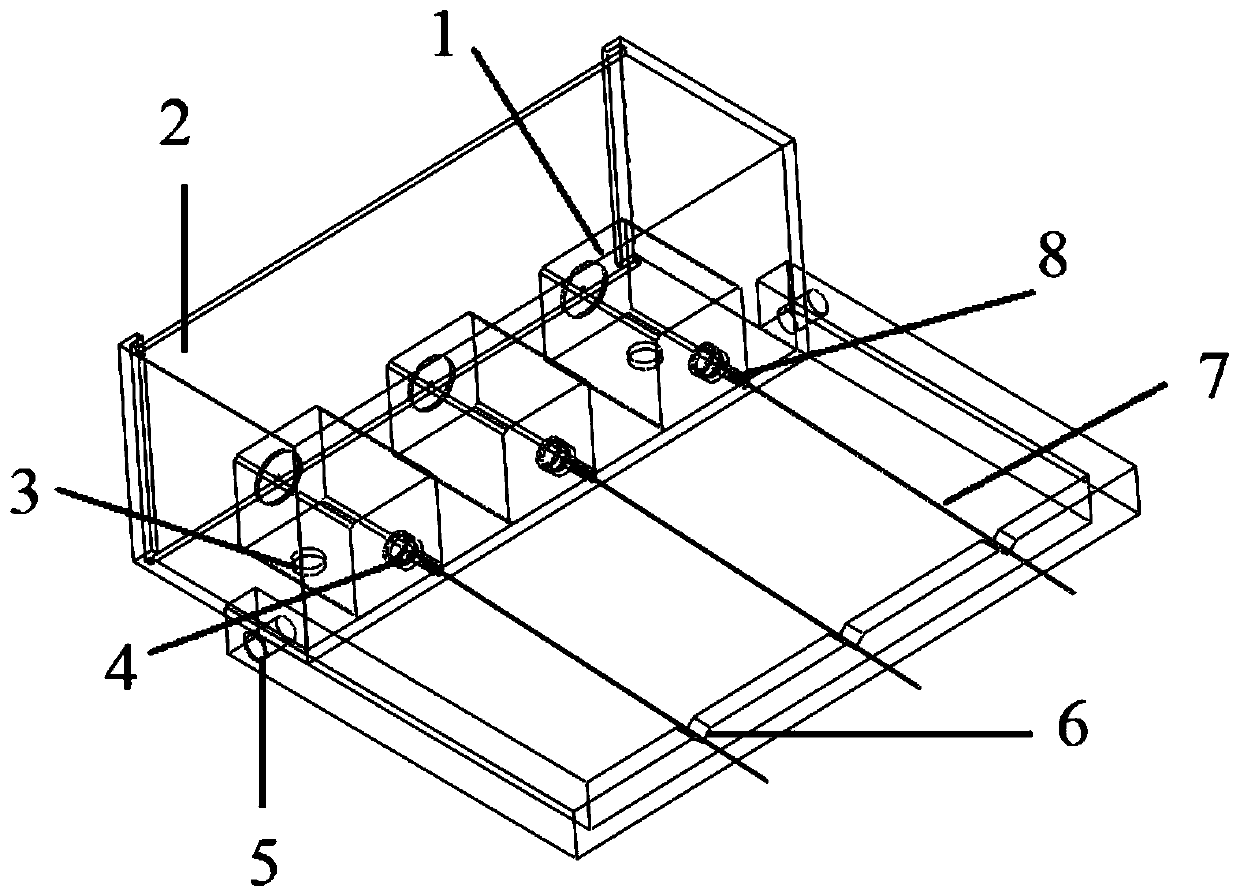
[0029] Such as figure 1 As shown, the optical fiber cylinder side uniform coating device according to an embodiment of the present invention is suitable for coating instruments with coating discs, including a protective rotating structure and an optical fiber supporting structure;

[0030] The protection rotating structure includes an outer frame closure 2, and its vertical side panel is combined with a bottom plate; a plurality of motors and power supply assemblies 1 are arranged on the bottom plate; the vertical side panel of the outer frame closure 2 It can be an integral structure, or it can be formed by plugging multiple side panels.

[0031] The optical fiber support structure includes an optical fiber holder fixed to the outer frame closure 2, and a plurality of V-shaped grooves 6 for placing optical fibers 7 are arranged on the optical fiber holder. ...


PUM


Abstract

The invention discloses a uniform coating device and method for the side of an optical fiber cylinder. The device is used on a coating instrument with a coating disc, and includes a protection rotation structure and an optical fiber support structure; the protection rotation structure includes an outer frame closure, which is erected The side panel is combined with a base plate; multiple motors and power supply components are arranged on the base plate; the optical fiber support structure includes an optical fiber support fixed to the outer frame closure, and a plurality of V-shaped grooves for placing optical fibers are arranged on it There are a plurality of small holes on the side of the vertical side wall facing the fiber support, corresponding to the motor output shafts of the motors and power supply components respectively; One end is tightly socketed with one end of the corresponding optical fiber; the other end of the optical fiber is placed on the V-shaped groove, so that the optical fiber rotates with the output shaft of the motor. The device of the invention has simple and compact structure, simple and easy method, and can be applied to various coating instruments.

Description

technical field [0001] The invention belongs to the technical field of optical fiber coating processing technology, and relates to an optical vacuum coating device and a method thereof, in particular to a uniform coating device and method for the cylindrical side of an optical fiber. Background technique [0002] The rapid development of optical fiber technology has led to the wide application of optical fiber in communication, sensing and other fields. In the field of optical communication, optical signal detection or transmission requires optical fibers to have a certain light reflection ability, and the conventional practice is to coat the optical fiber surface to improve the light reflection ability. In the field of optical sensing, optical fiber surface plasmon resonance sensor technology has received extensive attention and research. Surface plasmon resonance (Surface Plasmon Resonance, referred to as SPR) is a physical optical phenomenon that occurs at the interface b...

Claims


Application Information

Patent Timeline
Patent Type & Authority Patents(China)
IPC IPC(8): C23C14/50
CPCC23C14/505
Inventor 孙兵王旗韦玮胡二涛
Owner NANJING UNIV OF POSTS & TELECOMM
Why Eureka
Try Eureka