A Displacement Detection System for Substation GIS Expansion Joints
A displacement detection and expansion joint technology, which is applied in information technology support systems, circuit devices, electrical components, etc., can solve problems such as subjective judgment errors, no design warning mechanism, and inability to effectively ensure the safety of power grids and equipment. The effect of reducing signal interference
- Summary
- Abstract
- Description
- Claims
- Application Information
AI Technical Summary
Problems solved by technology
Method used
Image
Examples
Embodiment 1
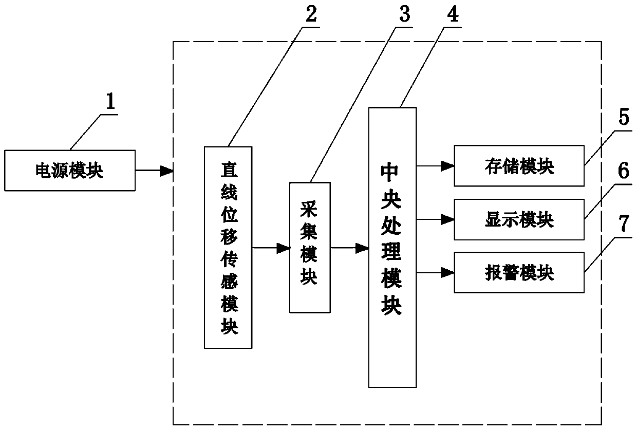
[0030] Such as figure 1 with figure 2 As shown, the present invention includes a power supply module 1, a linear displacement sensing module 2, an acquisition module 3, a central processing module 4, a storage module 5, a display module 6 and an alarm module 7, and the output terminal of the linear displacement sensing module 2 communicates through RS232 The module is connected with the input end of acquisition module 3, and the output end of acquisition module 3 is connected with central processing module 4 by RS485 communication module, and the output end of central processing module 4 is connected with storage module 5, display module 6 and alarm module 7 respectively connected to the input.
[0031] The effective stroke of the linear displacement sensing module 2 is 75-700mm. The two ends of the linear displacement sensing module 2 are provided with hanging rings 8, and the inner spherical hinges of the hanging ring 8 are connected to the bushing 9. They are installed at...
Embodiment 2
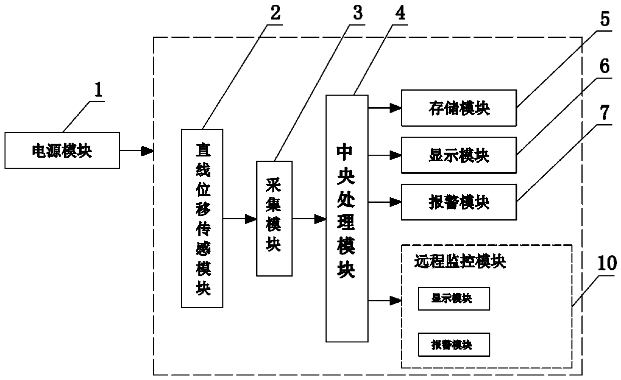
[0034] Such as image 3 As shown, the present invention includes a power supply module 1, a linear displacement sensing module 2, an acquisition module 3, a central processing module 4, a storage module 5, a display module 6, an alarm module 7 and a remote monitoring module 10, and the linear displacement sensing module 2 The output end is connected with the input end of the acquisition module 3 through the RS232 communication module, the output end of the acquisition module 3 is connected with the central processing module 4 through the RS485 communication module, and the output end of the central processing module 4 is respectively connected with the storage module 5 and the display module 6 Be connected with the input terminal of alarm module 7;
[0035] The remote monitoring module 10 is arranged in the monitoring room, and the central processing module 4 and the remote monitoring module carry out signal transmission through the Modbus protocol or Zigebee. The preferred Mo...
Embodiment 3
[0038] The structure of this embodiment is basically the same as that of Embodiment 2, the difference is: as Figure 4 As shown, the two ends of the GIS telescopic joint are fixedly connected to the positioning rod 11. When installed and used, the positioning rod 11 is sequentially provided with a limit nut 12, a first positioning ring 13 and a second positioning ring 14 from the outside to the inside. The limit nut 12 and the positioning The rod 11 is threaded and contacts the outer wall of the first locating ring 13, the first locating ring 13 is slidably connected with the locating rod 11, the second locating ring 14 is fixedly connected with the locating rod 11, the first locating ring 13 and the second locating ring 14 are all frustum-shaped structures, the end of the first positioning ring 13 with a smaller cross-sectional area is socketed with the end with a smaller cross-sectional area of the second positioning ring 14, and the end with a smaller cross-sectional area ...
PUM
 Abstract
Description
Claims
Application Information
 - R&D
- Intellectual Property
- Life Sciences
- Materials
- Tech Scout
- Unparalleled Data Quality
- Higher Quality Content
- 60% Fewer Hallucinations
Browse by: Latest US Patents, China's latest patents, Technical Efficacy Thesaurus, Application Domain, Technology Topic, Popular Technical Reports.
© 2025 PatSnap. All rights reserved.Legal|Privacy policy|Modern Slavery Act Transparency Statement|Sitemap|About US| Contact US: help@patsnap.com


