
Electric microfluidic droplet dispenser

A microfluidic and dispenser technology, applied in the field of experimental equipment, can solve problems such as large errors, and achieve low cost, less waste, and convenient and quick use

Active Publication Date: 2018-03-23
UNIV OF SCI & TECH OF CHINA
View PDF6 Cites 8 Cited by
  • Summary
  • Abstract
  • Description
  • Claims
  • Application Information

AI Technical Summary

Problems solved by technology

[0005] In order to solve the problem of excessive errors of existing dispensers / pipettors when operating smaller volumes of liquids, and realize the function of microfluidic droplet dispensers with the function of pumping liquids, this disclosure proposes a microfluidic printing-based electric Microfluidic droplet dispenser realizes liquid suction and liquid distribution, and can achieve sub-nano upgrade resolution

Method used


Image

  • Electric microfluidic droplet dispenser
  • Electric microfluidic droplet dispenser
  • Electric microfluidic droplet dispenser

Examples


Embodiment Construction

[0043] In order to make the purpose, technical solutions and advantages of the present disclosure clearer, the present disclosure will be further described in detail below in conjunction with specific embodiments and with reference to the accompanying drawings.

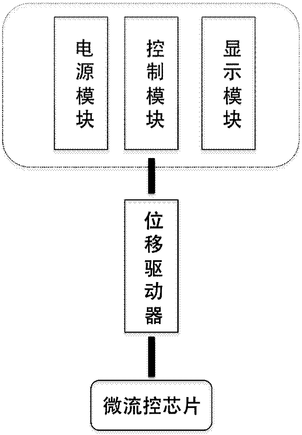
[0044] Such as figure 1 As shown, the electric microfluidic droplet dispenser of an embodiment of the present disclosure, the internal functional area of ​​the droplet dispenser includes three parts: a microfluidic chip as an ink cartridge for holding liquid, a displacement actuator, and a power supply The control system composed of module, control module and display module, the main functions of the control system are parameter input, result display and signal output.

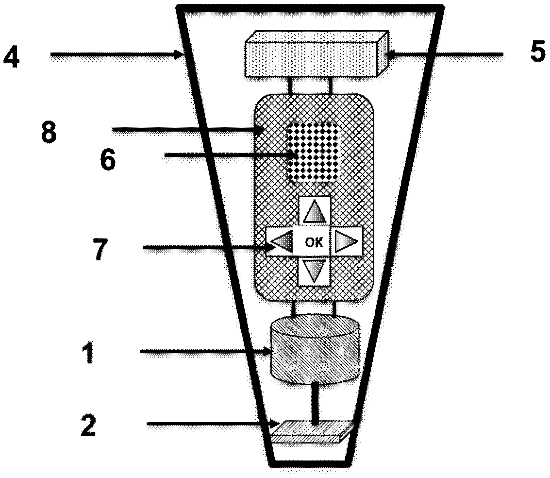
[0045] The droplet dispenser of this embodiment can be hand-held or desktop, and the power module can be either a built-in battery or an external power supply. For an example of a handheld drop dispenser powered by a built-in battery, see figure 2 ...


PUM


Abstract

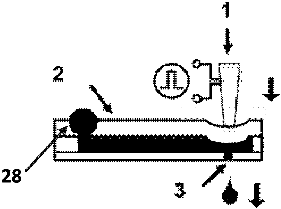
The present invention provides an electric microfluidic droplet dispenser. The dispenser prints liquid in a microfluidic chip into droplets with uniform volume based on a principle of microfluidic impact printing, and controls the loading volume by utilizing the number of times of printing, in other words, the number of droplets. A liquid is pre-injected into a replaceable microfluidic chip, and an electronic control system is used to set and control the number of printing droplets. With adoption of the electric microfluidic droplet dispenser of the invention, the volume of an individual droplet is smaller, typically is 0.1 nanoliter to 10 nanoliters, and a single droplet volume CV value is less than 3.4%. When sub-microliter volume loading is performed by multiple printing, the average effect further reduces the random error. The microfluidic chip is made of polymer materials, and thus is low in cost and replaceable. The microfluidic chip is isolated from an actuator, therefore cleaning is not needed and no cross-contamination exists. The remaining volume of a liquid is less than 1 microliter, therefore waste is less. A single-chip microcomputer is used to control the number of printing droplets, therefore automatic printing and liquid distribution are achieved; and the electric microfluidic droplet dispenser can extract a liquid as well as dispense a liquid, and thus is diversified in functions.

Description

technical field [0001] The disclosure belongs to the technical field of experimental instruments, and in particular relates to an electric microfluidic droplet dispenser, which is used for quantitative sampling, distribution and extraction of liquids. Background technique [0002] Liquid dispenser and pipette are hand-held instruments commonly used in biological and chemical laboratories to pipette a small amount of liquid. Their main working principle is to complete the transfer of liquid through the suction and extrusion of the piston: suction and discharge. This kind of pipette is also called "air displacement pipette", which uses the displacement of the sealed air cushion in the piston to suck and discharge the liquid. The original principle was proposed by Heinrich Schnitger as early as 1957 And applied for a patent. A series of patented technologies later created the basic structure and form of the modern pipette, such as the US patent "Pipettingsystem" (patent number:...

Claims


Application Information

Patent Timeline
IPC IPC(8): B01L3/00
CPCB01L3/5027B01L3/502707B01L2200/061B01L2300/0887B01L2300/12B01L2400/02B01L3/00B01L3/02
Inventor 李保庆禇家如毛宇盺李璇
Owner UNIV OF SCI & TECH OF CHINA
Learn More