Slag-iron separation method in initial stage of reblowing after long-time damping down of large blast furnace

A separation method and initial slag technology, applied in the field of smelting molten iron, can solve the problems affecting the recovery process of the blast furnace and the high risk of clogging of the skimmer, and achieve the effects of reducing heat consumption, not easy to deform, and good heat resistance

Inactive Publication Date: 2018-03-23
MAANSHAN IRON & STEEL CO LTD
View PDF4 Cites 1 Cited by
  • Summary
  • Abstract
  • Description
  • Claims
  • Application Information

AI Technical Summary

Benefits of technology

This patented technology relates to methods used during manufacturing processes that improve the efficiency or quality of steel making operations such as smelting reduction (SR), improving cool down capabilities, increasing lifecycle retention rates, enhancing energy savings, minimizing downtime costs associated therewith, and achieving better results through improved control over the movement of slags towards the melter vessel walls.

Problems solved by technology

The technical problem addressed in this Patented Technological Problem relates how to separate metal scrap from hot melt castings without leaving any residue behind inside them. Current methods involve manual cleanup processes involving workers walking around while removing scraps, leading to increased risks associated with accidents such as burning eyesight at the melter hearth area near the shaft. Additionally, current methods require frequent maintenance and may lead to unsafe conditions like explosions caused by flammable materials present within the smelter's tunnel.

Method used


Image

  • Slag-iron separation method in initial stage of reblowing after long-time damping down of large blast furnace
  • Slag-iron separation method in initial stage of reblowing after long-time damping down of large blast furnace

Examples


Embodiment 1

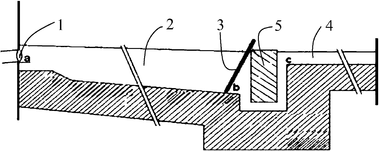
[0038] The method for separating iron and slag at the initial stage of re-airing after a long-term wind shutdown of a large-scale blast furnace in this embodiment includes the following specific steps:

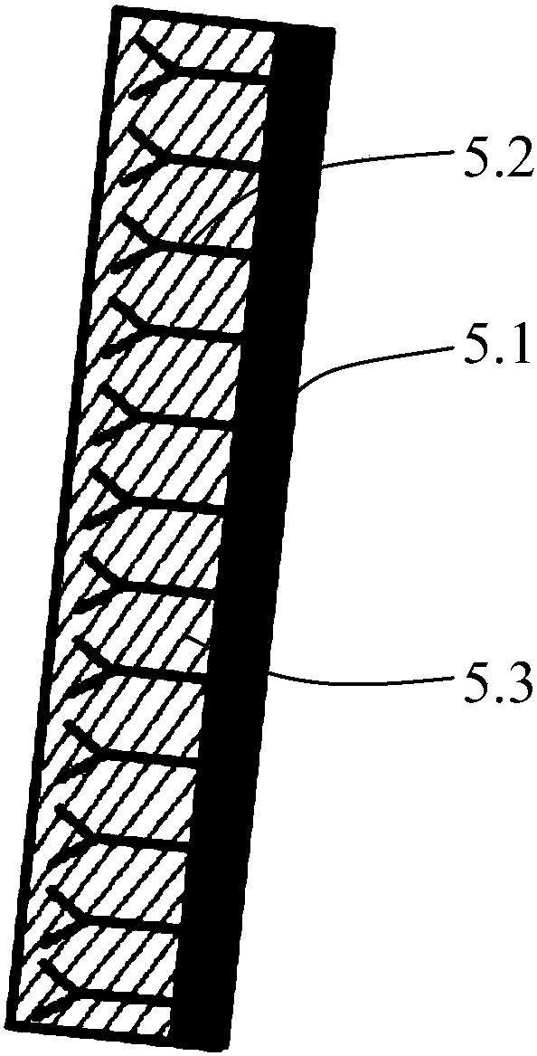
[0039] Step S101. Select a steel plate as the substrate. The steel plate is made of Q235-B or above grade material with a thickness of 10 mm. type, its effective height (the straight-line distance between two points) is 30cm, and the distance between the anchors is 300*300mm, and then the surface refractory material is poured, and the surface refractory material is consistent with the main groove refractory material The thickness of the castable is 50mm, which is a high-alumina castable, forming a baffle, and is dried for use;

[0040] Step S102, select a position 300mm upstream from the entrance of the small pit, insert the baffle into the main ditch obliquely, the inclination angle of the baffle is 60°, the upper part of the baffle leans against the support rod, and the refr...

Embodiment 2

[0045] The method for separating iron and slag at the initial stage of re-airing after a long-term wind shutdown of a large-scale blast furnace in this embodiment includes the following specific steps:

[0046] Step S101, select a steel plate as the substrate, the steel plate is made of Q235-B or above material with a thickness of 12mm, and its width is less than the width of the main groove by 20mm, wherein a number of through holes are opened on the steel plate, and the anchor piece includes a rod body and a nut. The rod body of the anchor passes through the through hole, and there is a nut on each side to fix it. The head of the anchor is Y-shaped, and its effective height (the straight-line distance between two points) is 30cm. The distance between the anchors is 300*300mm , and then cast the board surface refractory material, the board surface refractory material is consistent with the main groove refractory material, the thickness of the board surface refractory material ...

Embodiment 3

[0051] The method for separating iron and slag at the initial stage of re-airing after a long-term wind shutdown of a large-scale blast furnace in this embodiment includes the following specific steps:

[0052] Step S101, select a steel plate as the substrate, the steel plate is made of Q235-B or above grade material with a thickness of 15mm, and its width is less than 15mm of the main groove width, wherein a number of through holes are opened on the steel plate, and the anchor piece includes a rod body and a nut. The rod body of the anchor passes through the through hole, and there is a nut on each side to fix it. The head of the anchor is Y-shaped, and its effective height (the straight-line distance between two points) is 25cm. The distance between the anchors is 300*300mm , and then cast the plate surface refractory material, the plate surface refractory material is consistent with the main groove refractory material, the thickness of the plate surface refractory material i...


PUM


Abstract

The invention discloses a slag-iron separation method in an initial stage of reblowing after long-time damping down of a large blast furnace, and belongs to the technical field of molten iron smelting. The method comprises the following steps: (S101) a substrate is provided with an anchorage piece; then, a board refractory is poured; the thickness of the board refractory is larger than the heightof the anchorage piece; and a baffle plate is formed and dried for future use; (S102) a distance small pit is selected to enter the upstream; the baffle plate is aslant inserted in a main ditch; the board refractory faces an iron notch; and a gap between the baffle plate and the side of the main ditch is fully filled and compacted by yellow sand; (S103) the iron notch is opened; and when more slagor weak fluidity of the molten iron is generated during tapping, the baffle plate is not shifted, and slag and iron are discharged into a dry slag pit through a slag groove; and (S104) when the fluidity of the molten iron is normal, the baffle plate is pulled away, and the molten iron passes through a slag remover to enter a tank. The iron slag with weaker fluidity in the initial stage of reblowing after long-time damping down of the large blast furnace can be safely discharged, so that the heat consumption in the furnace is reduced, the recovery progress of the blast furnace is accelerated,the next discharge of the molten iron is fully prepared, and the smooth recovery progress of the blast furnace is guaranteed.

Description


Claims


Application Information

Patent Timeline
Owner MAANSHAN IRON & STEEL CO LTD
Why Eureka
Try Eureka