A multi-angle installation type industrial handling robot

A multi-angle handling robot technology, applied in the direction of manipulators, manufacturing tools, claw arms, etc., can solve the problems of difficult heat dissipation of servo motors, low precision of cylinder transmission, and uneven clamping weight, etc., to achieve excellent results and precision High degree, increase market competitiveness and production cost, and long service life

Active Publication Date: 2019-09-13
WUXI IDO SCI & TECH CO LTD
View PDF6 Cites 0 Cited by
  • Summary
  • Abstract
  • Description
  • Claims
  • Application Information

AI Technical Summary

Problems solved by technology

Typical applications of industrial robots include welding, painting, assembly, collection and placement, product inspection and testing, etc.; all work is completed with high efficiency, durability, speed and accuracy, and industrial robots in the prior art are all The clamping of the clamping mechanism is controlled by the cylinder, but the transmission accuracy of the cylinder is not high, which may easily lead to different clamping weights, and the transmission mode of the rack and pinion will bring greater friction, resulting in greater power required and wasting energy. , and the wear and tear is large, the service life is low, and the industrial robot can only work and install at a fixed height. When it is necessary to clamp items of different heights, it needs to be installed on other machines for use, which is not only inconvenient, but also increases cost, and the heat generated by the servo motor is difficult to dissipate evenly during work. In view of this, we propose a multi-angle installation industrial handling robot

Method used


Image

  • A multi-angle installation type industrial handling robot
  • A multi-angle installation type industrial handling robot
  • A multi-angle installation type industrial handling robot

Examples


Embodiment Construction

[0031]The following will clearly and completely describe the technical solutions in the embodiments of the present invention with reference to the accompanying drawings in the embodiments of the present invention. Obviously, the described embodiments are only some, not all, embodiments of the present invention. Based on the embodiments of the present invention, all other embodiments obtained by persons of ordinary skill in the art without making creative efforts belong to the protection scope of the present invention.

[0032] see Figure 1-9 , the present invention provides a technical solution:

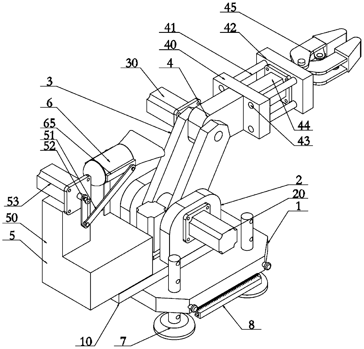
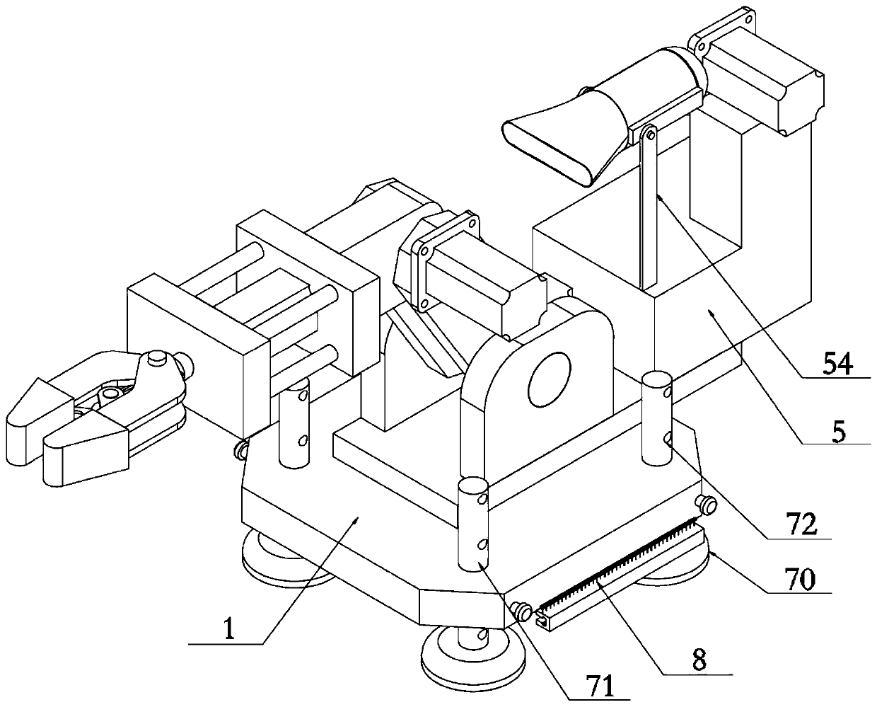
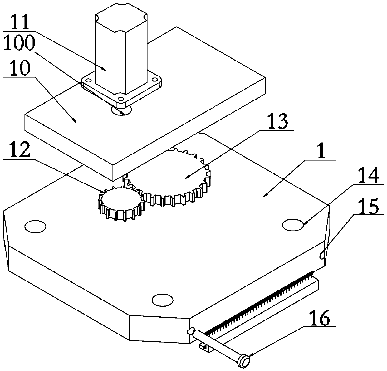
[0033] A multi-angle installation type industrial handling robot, including a fixed seat 1, the surface of the fixed seat 1 is provided with a rotating seat 10, the surface of the rotating seat 10 is provided with a first servo motor 11, the output shaft of the first servo motor 11 passes through the rotating The motor shaft hole 100 on the seat 10 is coaxially provided with a pini...


PUM


Abstract

The invention relates to the technical field of industrial machinery, in particular to a multi-angle installation type industrial carrying robot. The robot comprises a fixed seat, wherein a rotating seat is arranged on the surface of the fixed seat; a first joint is arranged on the surface of the rotating seat; one end of the first joint is provided with a main arm and is rotationally connected with one end of the main arm; one end of the main arm is provided with a second joint and is rotationally connected with the second joint; a first fixing block is arranged at one end of the second joint; a second fixing block parallel to the first fixing block is arranged on one side of the first fixing block; a clamping jaw assembly is arranged at one end of the second fixing block; lifting mechanisms are arranged at the four corners of the rotating seat correspondingly; a clamping installing mechanism is arranged at the bottom end of the rotating seat; a supporting seat is arranged on the surface of the rotating seat; and a heat dissipation device is arranged above the supporting seat. According to the multi-angle installation type industrial carrying robot, clamping installing can be realized for any different mechanisms, and adaptability is strong; and only one heat dissipation device is needed to dissipate heat of motors and the joint friction of the various joints of the whole robot, thus heat dissipation of the robot in the working process is carried out uniformly, and the service life of the robot is prolonged.

Description

technical field [0001] The invention relates to the technical field of industrial machinery, in particular to a multi-angle installation type industrial handling robot. Background technique [0002] An industrial robot is a multi-joint manipulator or a multi-degree-of-freedom robot for the industrial field. It is a machine device that performs work automatically, and a machine that realizes various functions by its own power and control capabilities. It consists of three basic parts: the main body, the drive system and the control system. It can be commanded by humans or run according to pre-programmed programs. Modern industrial robots can also act according to the principles and programs formulated by artificial intelligence technology. Typical applications of industrial robots include welding, painting, assembly, collection and placement, product inspection and testing, etc.; all work is completed with high efficiency, durability, speed and accuracy, and industrial robot...

Claims


Application Information

Patent Timeline
Patent Type & Authority Patents(China)
IPC IPC(8): B25J17/02B25J18/00B25J11/00B25J19/00
Inventor 周利锋
Owner WUXI IDO SCI & TECH CO LTD
Why Eureka
Try Eureka