Electric roller permanent magnet motor

A technology of permanent magnet motor and electric drum, applied in the direction of magnetic circuit rotating parts, magnetic circuit static parts, magnetic circuit shape/style/structure, etc. problems, to achieve the effect of small positioning force and rotational inertia, large magnetic conduction area, and light weight of the motor

Active Publication Date: 2018-03-27
TANGSHAN WEISEN NEW MATERIAL CO LTD
View PDF6 Cites 1 Cited by
  • Summary
  • Abstract
  • Description
  • Claims
  • Application Information

AI Technical Summary

Problems solved by technology

[0004] At present, the motors used in electric drum tubes are permanent magnet DC motors and asynchronous motors, but DC motors with carbon brush slip ring structures are prone to sparks, which are not suitable for use in high-risk mines. The asynchronous motor has a large current and torque when starting. relatively low

Method used


Image

  • Electric roller permanent magnet motor
  • Electric roller permanent magnet motor
  • Electric roller permanent magnet motor

Examples


Embodiment Construction

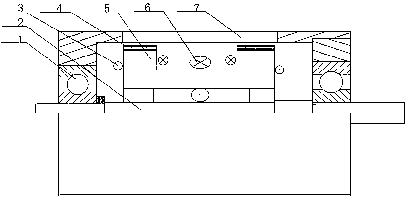
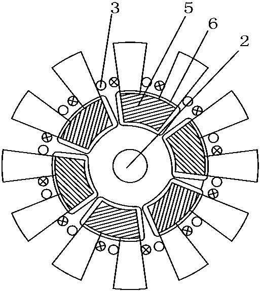
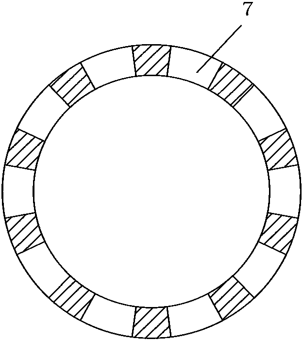
[0025] figure 1 It is a longitudinal cross-sectional view of a permanent magnet motor of the electric drum motor when the flux linkage is minimum. Among them, 1 bearing, 2 shafts, 3 armature windings, 4 permanent magnets, 5 stator cores, 6 field windings, and 7 rollers.

[0026] A permanent magnet motor for electric drum, which is characterized in that the drum is mounted on the shaft through a bearing and can rotate around the shaft, and 5K rectangular holes are evenly distributed on the circumferential surface of the drum. K is a positive integer, where k=2, rectangular when viewed from the side The holes are fan-shaped.

[0027] The stator core is fixed in the middle of the shaft. The stator core is composed of 3K evenly distributed "匚"-shaped sub-stator cores. The yoke in the middle of the sub-stator core is parallel to the axis; each sub-stator core has two stator teeth at each end. The sides of the stator teeth are sector-shaped; all the stator teeth face the outside of the ...


PUM


Abstract

The invention discloses an electric roller permanent magnet motor, which belongs to the technical field of electric rollers. The electric roller permanent magnet motor comprises a shaft, a roller, a stator core, armature windings, excitation windings, permanent magnets, rotor teeth and a bearing, wherein the circumferential surface of the roller is uniformly distributed with 5K rectangular holes;the stator core is formed by 3K uniformly-distributed [-shaped sub stator cores; two ends of each sub stator core are provided with two stator teeth respectively; all stator teeth face the outer sideof the circumference, and the distance between the stator teeth at two ends of the same sub stator core is smaller than the axial length of the rectangular hole of the roller; the surface of the stator tooth at one end of the sub stator core is provided with a permanent magnet; and each stator tooth is wound with an integrated armature winding. Thus, integrated design between the roller and a driving motor can be effectively realized, cooling is easy, advantages of integrated excitation can be made full use of, and high application value in the electric roller is realized.

Description

Technical field [0001] The invention relates to a permanent magnet motor for electric drums, belonging to the technical field of electric drums. Background technique [0002] Electric drum is the main part of belt conveyor and lifting equipment to transmit power. It has compact structure, small space occupation, high transmission efficiency, and good sealing performance. It is suitable for working in humid and dusty environments. The power of the electric drum comes from the motor, and its reliability determines the safe use of the electric drum. [0003] At present, most of the motors used in electric drums are internal rotor motors, which require a gear reducer to transmit power to the drum outer body, so the mechanical structure is relatively complicated and bulky. For example, the application number is 200910266590.1: a drum motor stator structure. The application adopts a bar-shaped stator core structure, which increases the volume of the coil winding in the stator slot, impr...

Claims


Application Information

Patent Timeline
Patent Type & Authority Applications(China)
IPC IPC(8): H02K1/17H02K1/22
Inventor 史立伟刘金刚杨玉峰侯振煜陈渠先李同旺郑志远
Owner TANGSHAN WEISEN NEW MATERIAL CO LTD
Why Eureka
Try Eureka