
Machining center scrap iron compression equipment

A technology for processing centers and compression equipment, which is applied to metal processing equipment, metal processing machinery parts, presses, etc., can solve the problems of large space occupied by iron filings and troublesome collection, and achieve the solution of large occupied space, reduced occupied space, The effect of reducing friction

Inactive Publication Date: 2018-03-30
江苏万通塑业有限公司
View PDF0 Cites 9 Cited by
  • Summary
  • Abstract
  • Description
  • Claims
  • Application Information

AI Technical Summary

Problems solved by technology

[0005] Aiming at the deficiencies of the prior art, the present invention provides a kind of iron filings compression equipment for machining centers, which solves the problem that iron filings occupy a large space and are troublesome to collect

Method used

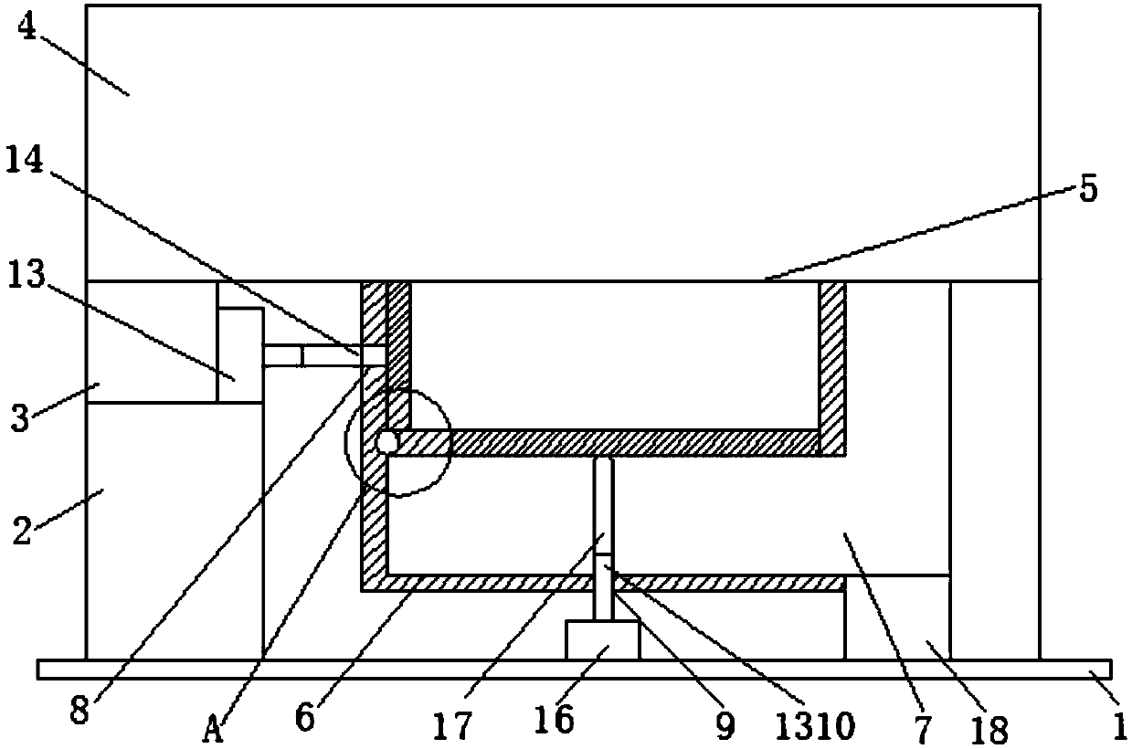
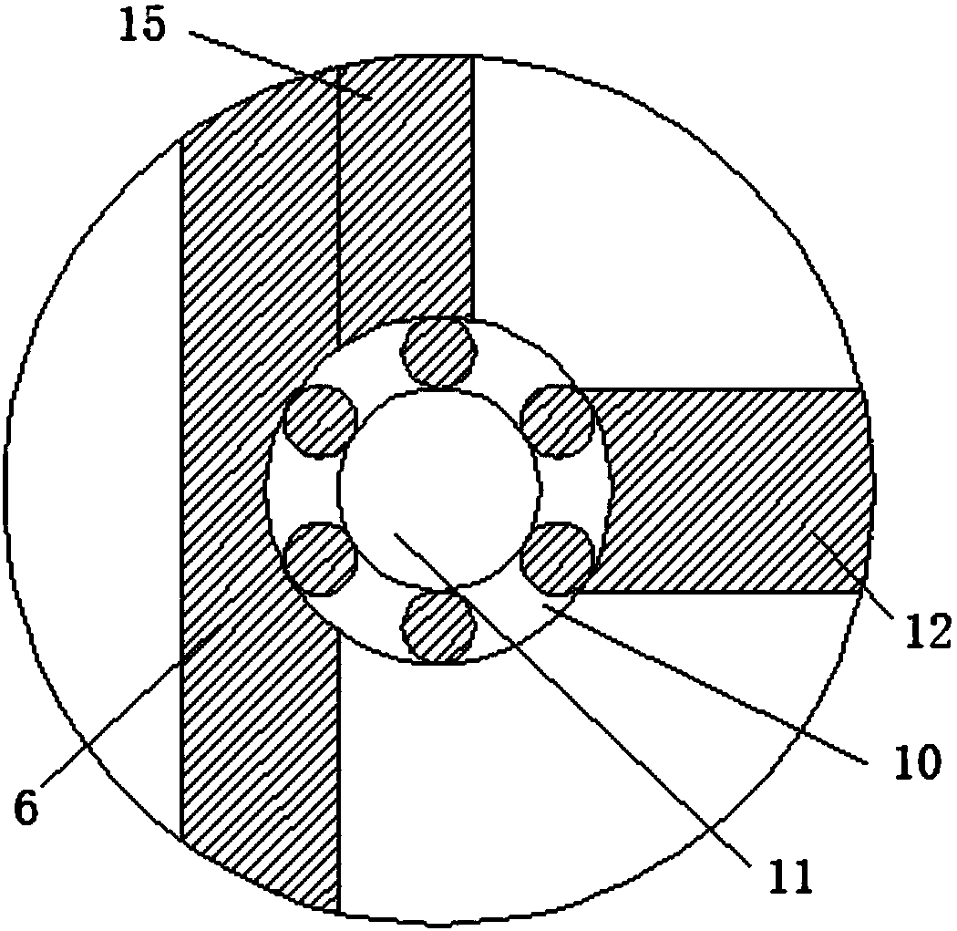
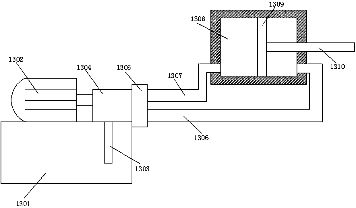

Image

  • Machining center scrap iron compression equipment
  • Machining center scrap iron compression equipment
  • Machining center scrap iron compression equipment

Examples


Embodiment Construction

[0023] The following will clearly and completely describe the technical solutions in the embodiments of the present invention with reference to the accompanying drawings in the embodiments of the present invention. Obviously, the described embodiments are only some, not all, embodiments of the present invention. Based on the embodiments of the present invention, all other embodiments obtained by persons of ordinary skill in the art without making creative efforts belong to the protection scope of the present invention.

[0024] see Figure 1-3 , the present invention provides a technical solution: a chip compression equipment for a machining center, including a base 1, the upper surface of the base 1 is slidingly connected with a discharge box 18, and the upper surface of the discharge box 18 is connected to the bottom of the chip box 6 Sliding connection, the upper surface of the base 1 is fixedly connected with the support leg 2, the upper surface of the support leg 2 is fix...


PUM


Abstract

The invention discloses an iron filings compression device for a machining center, comprising a base, the upper surface of the base is fixedly connected with a support leg, the upper surface of the support leg is fixedly connected with a support platform, and the upper surface of the support platform is fixedly installed with a machining center, The bottom of the machining center is provided with an iron filings port, the bottom of the machining center is fixedly connected with an iron filings box, the side of the iron filings box is provided with a discharge port, and the side of the iron filings box is opened with a first hydraulic hole. The iron chip compression equipment of the machining center is fixedly installed with a first hydraulic device on the side of the support table, one end of the first hydraulic device is fixedly connected with the first connecting rod, and one end of the first connecting rod is fixedly connected with the first baffle plate, and the first hydraulic device is fixedly connected with the first connecting rod. The top of the second hydraulic device is fixedly connected with a second connecting rod, and the upper surface of the second connecting rod is slidably connected with a second baffle, which compresses the iron filings and reduces the occupied space of the iron filings, thus effectively solving the problem of iron filings occupation. Large space to collect troublesome issues.

Description

technical field [0001] The invention relates to the technical field of machining centers, in particular to iron chip compression equipment for machining centers. Background technique [0002] Machining centers are developed from CNC milling machines. The biggest difference from the CNC milling machine is that the machining center has the ability to automatically exchange machining tools. By installing different-purpose tools on the tool magazine, the machining tool on the spindle can be changed through an automatic tool changer in one clamping to achieve a variety of machining. Features. [0003] At present, the processing centers on the market do not compress the iron filings after processing the raw materials, which makes the iron filings take up a lot of space and is troublesome to collect. Contents of the invention [0004] (1) Solved technical problems [0005] Aiming at the deficiencies of the prior art, the present invention provides an iron filings compression d...

Claims


Application Information

Patent Timeline
Patent Type & Authority Applications(China)
IPC IPC(8): B23Q11/00B30B9/32
CPCB23Q11/0057B30B9/327
Inventor 毛永远
Owner 江苏万通塑业有限公司
Learn More