Transverse magnetic field outer rotor switch reluctance motor

A technology of switched reluctance motor and transverse magnetic field, applied in the direction of magnetic circuit rotating parts, magnetic circuit, electric components, etc., can solve the problems of high cost, small output total torque, complex controller structure, etc., and achieve low manufacturing cost, The effect of small working vibration and simple structure

Inactive Publication Date: 2018-03-30
LUSHAN COLLEGE OF GUANGXI UNIV OF SCI & TECH
View PDF8 Cites 0 Cited by
  • Summary
  • Abstract
  • Description
  • Claims
  • Application Information

AI Technical Summary

Problems solved by technology

[0011] The technical problem to be solved by the present invention is to provide a switched reluctance motor with a transverse magnetic field outer rotor to solve the shortcomings of the existing switched reluctance motors such as small output torque, complicated controller structure and high cost

Method used


Image

  • Transverse magnetic field outer rotor switch reluctance motor
  • Transverse magnetic field outer rotor switch reluctance motor
  • Transverse magnetic field outer rotor switch reluctance motor

Examples


Embodiment 1

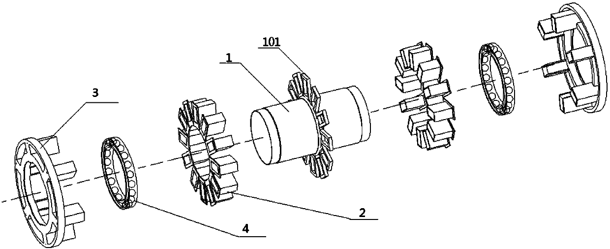
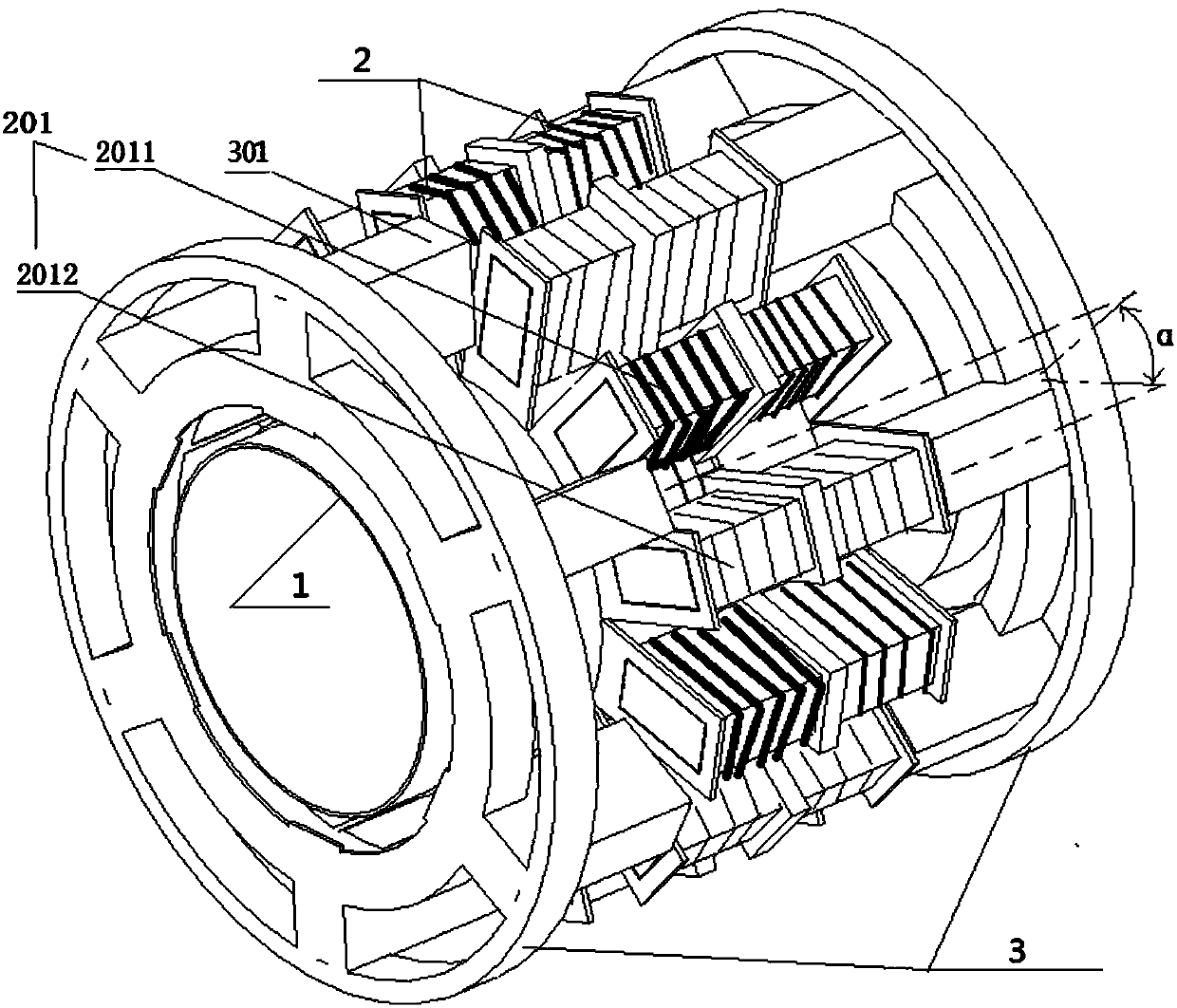
[0044] A transverse magnetic field external rotor switched reluctance motor, including a stator 2, a rotor 3, and a stator sleeve 1, a rotor sleeve 5; the stator sleeve 1 is equipped with a stator positioning frame 101; the stator 2. There are two sets of rotors 3, each set of rotors 3 has n=6 rotating poles, and each set of stators 2 has 2×n total of 12 magnetic poles; two sets of stators 2 are respectively installed on both sides of the stator positioning frame 101 On the stator sleeve 1, and each set of stator 2 is installed between two adjacent magnetic poles, a photoelectric commutator 202 for controlling the winding current of the stator coil; two sets of rotors 3 are respectively installed on the two sets of stators 2 through bearings 4 , and the two sets of rotors 3 are staggered by an angle α in the vertical plane of the axis, α=360° / 4n=15°; each set of rotors 3 includes n=6 groups of silicon steel sheet assembly blocks 301; the rotor sleeve 5 is tightly fitted on the...


PUM


Abstract

The invention discloses a transverse magnetic field outer rotor switch reluctance motor, and relates to a switch reluctance motor which comprises two stators, two rotors, stator sleeves and rotor sleeves. A stator positioning frame is mounted on the stator sleeves, each rotor is provided with n rotor poles, each stator is provided with 2n magnetic poles, the two stators are mounted on the stator sleeves on two sides of the stator positioning frame, a photoelectric phase changer for controlling the current of a stator coil winding is mounted between two adjacent magnetic poles of each stator, the two rotors are mounted on the outer sides of the two stators through bearings and staggered by an angle alpha in a vertical surface of an axis, and alpha is equal to 360 degrees / 4n. The rotor sleeves closely sleeve outer peripheries of the two rotors, and the inner diameters of the rotor sleeves are larger than the outer diameters of the stators. The transverse magnetic field outer rotor switchreluctance motor can solve the problems of small total output torque, complicated controller structure and high cost of an existing switch reluctance motor, and is easy to popularize and use.

Description

technical field [0001] The invention relates to a switched reluctance motor, in particular to a switched reluctance motor with a transverse magnetic field outer rotor. Background technique [0002] Switched reluctance motor is a new type of speed regulating motor. Its speed regulating system has the advantages of both DC and AC speed regulating systems. It is the latest generation of stepless speed regulating system following frequency conversion speed regulating system and brushless DC motor speed regulating system. . It has simple and firm structure, wide speed regulation range, excellent speed regulation performance, high efficiency in the whole speed regulation range, and high system reliability. However, the switched reluctance motor also has some disadvantages, mainly: large vibration under working conditions, complex structure of the circuit control part, high manufacturing cost, and the working torque needs to be further improved. [0003] (1) Vibration is relative...

Claims


Application Information

Patent Timeline
Patent Type & Authority Applications(China)
IPC IPC(8): H02K16/00H02K1/14H02K1/22H02K3/28H02K13/04H02K11/20
CPCH02K1/145H02K1/22H02K3/28H02K11/20H02K13/04H02K16/00
Inventor 伊双清
Owner LUSHAN COLLEGE OF GUANGXI UNIV OF SCI & TECH
Why Eureka
Try Eureka