Underground intercom system

A technology of intercom system and conversion unit, which is applied in the field of communication, can solve problems affecting communication quality and transmission distance, and achieve the effects of lighting and communication, high response sensitivity, and good modulation performance

Inactive Publication Date: 2018-03-30
重庆市万盛区杜宇机电有限责任公司
0 Cites 3 Cited by

AI-Extracted Technical Summary

Problems solved by technology

In addition, mining equipment and exhaust facilities are placed under the mine, and a large number of barbed wires are distributed on and around the...

Abstract

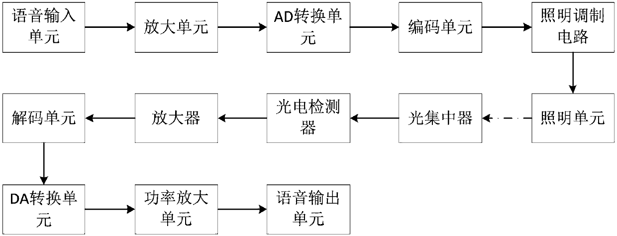
The invention provides an underground intercom system, which includes a voice input unit, an amplification unit, an AD conversion unit, a coding unit, a lighting modulation circuit, a lighting unit, an optical concentrator, a photoelectric detector, an amplifier, a decoding unit, a DA conversion unit, a power Amplifying unit and voice output unit. The transmitter sends the collected analog audio signal to the control unit for amplification, AD conversion and Manchester encoding, and the digital signal is loaded to the lighting modulation drive circuit. The optical concentrator converges the optical signal to the photosensitive surface of the photodetector, the optical signal is converted into an electrical signal, and regenerated into the original Manchester coded signal, and then the signal is decoded and DA converted by the control unit. Finally, the signal is amplified and loaded onto the small speaker to restore the voice signal. The invention utilizes the outstanding advantages of high LED response sensitivity and good modulation performance to realize visible light wireless communication of LED miner's lights, and the background conditions of underground darkness and low reflection intensity are conducive to the transmission of visible light, and can realize both lighting and communication.

Application Domain

Technology Topic

Image

  • Underground intercom system
  • Underground intercom system
  • Underground intercom system

Examples

  • Experimental program(1)

Example Embodiment

[0019] The embodiments of the present invention are described below through specific specific examples, and those skilled in the art can easily understand other advantages and effects of the present invention from the contents disclosed in this specification. The present invention can also be implemented or applied through other different specific embodiments, and various details in this specification can also be modified or changed based on different viewpoints and applications without departing from the spirit of the present invention. It should be noted that the following embodiments and features in the embodiments may be combined with each other under the condition of no conflict.
[0020] It should be noted that the drawings provided in the following embodiments are only used to illustrate the basic concept of the present invention in a schematic way, so the drawings only show the components related to the present invention rather than the number, shape and number of components in actual implementation. For dimension drawing, the type, quantity and proportion of each component can be changed at will in actual implementation, and the component layout may also be more complicated.
[0021] like figure 1 As shown, an underground intercom system includes a transmitter and a receiver;
[0022] The transmitting end includes a voice input unit, an amplifying unit, an AD conversion unit, an encoding unit, an illumination modulation circuit, and an illumination unit;
[0023] The receiving end includes an optical concentrator, a photodetector, an amplifier, a decoding unit, a DA conversion unit, a power amplifying unit and a voice output unit;
[0024] The voice input unit is used to collect the sound signal that needs to be transmitted and convert the sound signal into an analog audio signal. The amplifying unit amplifies the analog audio signal, and the amplified analog audio signal is converted into a first digital signal by the AD conversion unit. The digital signal is Manchester encoded to generate a second digital signal, the second digital signal is loaded into the lighting modulation circuit, and the lighting modulation circuit modulates the light emitted by the light-emitting unit to make the invention unit emit light as required;
[0025] The light concentrator gathers the light signal emitted by the light-emitting unit onto the photodetector and converts it into an electrical signal. The electrical signal is generated by the amplifier and the decision circuit to generate the original Manchester encoded signal. The decoding unit decodes the original Manchester encoded signal, and the decoding generates The signal is converted into an analog signal by the DA conversion unit, and the analog signal is amplified by the power amplifying unit and output to the voice output unit.
[0026] The speech input unit is a functional device capable of collecting speech, and the speech output unit is a device that outputs speech.
[0027] In this embodiment, the voice input unit is a microphone, and the voice output unit is a speaker. The lighting unit is an LED.
[0028] According to the special environment in the mine and the characteristics of the white LED visible light communication technology, the present invention provides an intercom system with both lighting and voice communication functions. The system is mounted on a miner's lamp cap, which is used by miners for lighting and voice communication. When the two miners need to communicate, they speak through the microphone, and the voice signal of the microphone is modulated to the LED light of the miner's hat to emit; it is irradiated on the optical receiver on the top of the miner's hat, converted into an electrical signal, and restored to a voice signal after processing. communication. The working principle of the system: the voice analog signal is converted into a digital signal, and then the signal is encoded to be suitable for system transmission, the encoded signal is modulated onto the LED, and sent out through the visible light (wavelength of 380-780nm) carrier; the optical signal is transmitted through the space channel and received. The machine receives and performs photoelectric conversion, and then the electrical signal is restored to the original encoded digital signal, and finally the signal is decoded and converted into a voice analog signal. When the system is in communication, it does not affect the lighting; when it is not in communication, the communication module enters the sleep state (reducing system power consumption), and does not affect the lighting of the LED miner's lamp.
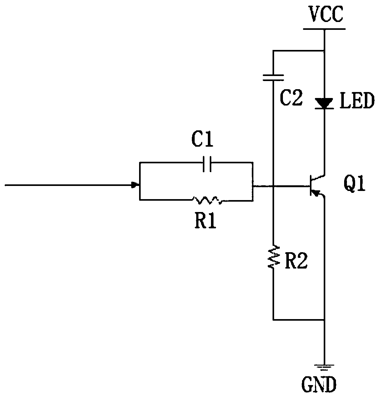
[0029] In order to realize the dual use of lighting and communication on the LED miner's lamp, it is necessary to improve the driving circuit of the LED miner's lamp to complete the lighting and modulation functions and switching. When there is a voice signal, the LED can be used for both lighting and communication; when there is no voice signal, the LED illuminates with maximum efficiency. The specific circuit diagram is as follows figure 2 shown.
[0030] like figure 2 As shown, the lighting modulation circuit includes a first capacitor, a second capacitor, a first resistor, a second resistor and a triode, the second capacitor is connected in series with the second resistor, and the first resistor is connected in parallel with the first capacitor and then connected to The common node of the second capacitor and the second resistor, the second capacitor is connected in parallel between the anode of the LED and the base of the triode, the second resistor is connected in parallel between the base of the triode and the emitter of the triode, the LED The negative electrode is connected to the collector electrode of the triode.
[0031] When the signal is 1, the voltage across the LED is higher than Vg, and the LED is on; when the signal is 0, the voltage across the LED is lower than Vg, and the LED is off. And when there is no signal, the lighting circuit should ensure the normal lighting of the LED. The working flow of the lighting modulation circuit is as follows: when there is no signal, the modulation circuit is disconnected and the lighting circuit is working; and when there is a signal, the lighting circuit is disconnected and the modulation circuit is working.
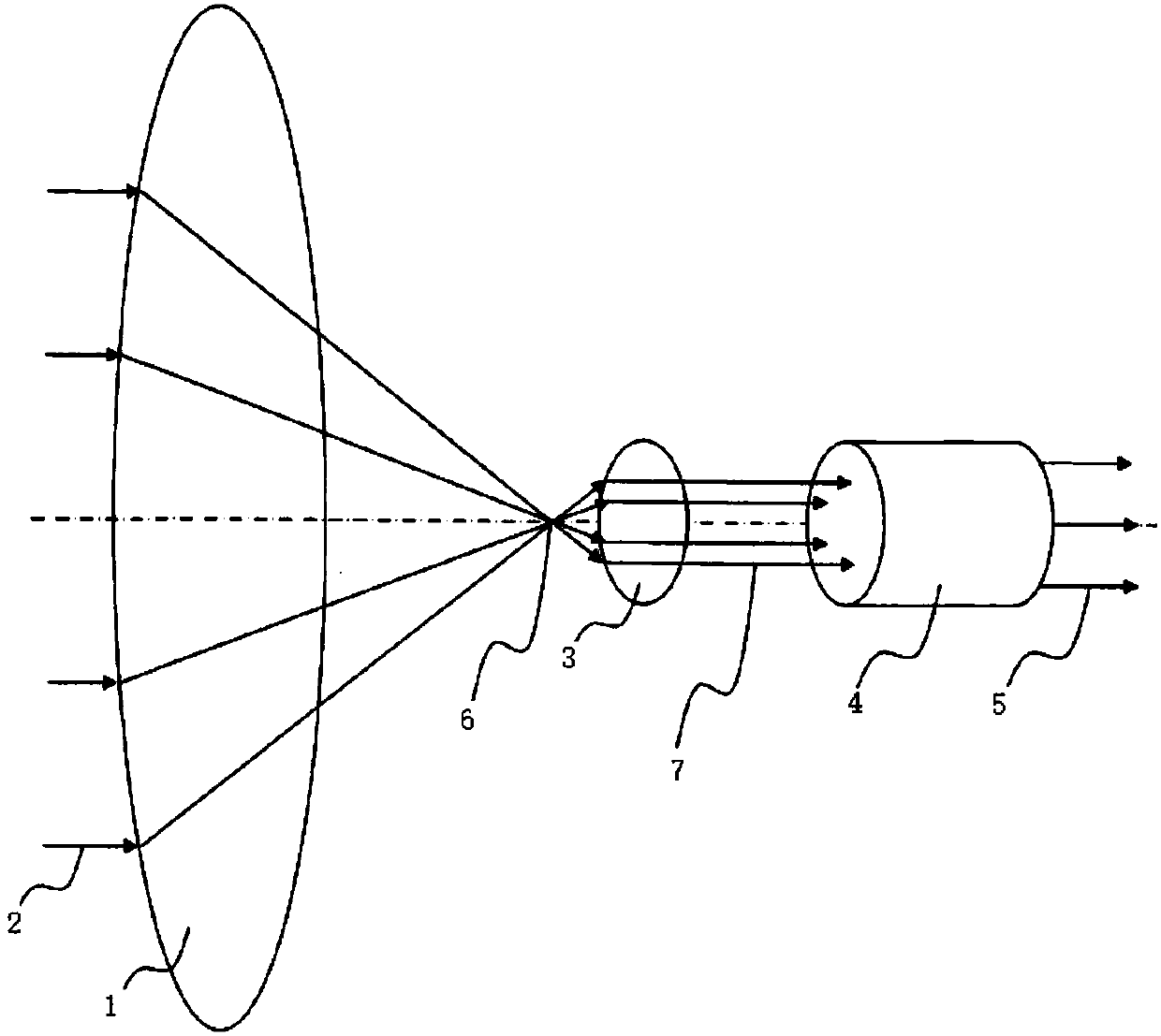
[0032] image 3 It is a structural diagram of the light concentrator. As shown in the figure, the light concentrator includes a first convex lens 1, a second convex lens 3 and an optical fiber 4. The first convex lens condenses the light emitted by the lighting unit, and the second convex lens The optical fiber transmits the light transmitted by the second convex lens for directing the light condensed by the first convex lens.
[0033] The natural light 2 is irradiated on the first convex lens 1. Since the natural light such as sunlight is far away from the earth, the sunlight can be regarded as a parallel light. According to the optical principle, the parallel light is refracted by the convex lens 1 and then converges to the focus 6 of the first convex lens 1. Then, use a second convex lens 3 whose optical surface is much smaller than that of the first convex lens 1 to receive the converged light. The focal points of the convex lenses of a convex lens 1 are coincident, and the optical axes are coincident, such as the focal point 6 in the figure. Then, the parallel light 7 emitted from the second convex lens 3 is introduced into a bundle of optical fibers or optical cables 4 for transmission. Since the incident light rays are parallel rays, they are directly injected into the optical fibers or optical cables 4 transmitted by the light guide, which can ensure that the optical fibers or optical fibers in the optical cable 4 are transmitted. Complete total reflection is realized on the tube wall, which improves transmission efficiency, and at the same time, the light 5 emitted from the optical fiber or optical cable 4 is a bundle of high-brightness light that is collected and transmitted.
[0034] The above-mentioned embodiments merely illustrate the principles and effects of the present invention, but are not intended to limit the present invention. Anyone skilled in the art can modify or change the above embodiments without departing from the spirit and scope of the present invention. Therefore, all equivalent modifications or changes made by those with ordinary knowledge in the technical field without departing from the spirit and technical idea disclosed in the present invention should still be covered by the claims of the present invention.

PUM

no PUM

Description & Claims & Application Information

We can also present the details of the Description, Claims and Application information to help users get a comprehensive understanding of the technical details of the patent, such as background art, summary of invention, brief description of drawings, description of embodiments, and other original content. On the other hand, users can also determine the specific scope of protection of the technology through the list of claims; as well as understand the changes in the life cycle of the technology with the presentation of the patent timeline. Login to view more.

Similar technology patents

Classification and recommendation of technical efficacy words

Why Eureka
Try Eureka