Lubricant injector for large slow-running two-stroke engine and production method

A syringe and two-stroke technology, applied in the field of syringes, can solve problems such as increased wear and tear

Active Publication Date: 2018-04-03
HANS JENSEN LUBRICATORS
View PDF19 Cites 0 Cited by
  • Summary
  • Abstract
  • Description
  • Claims
  • Application Information

AI Technical Summary

Problems solved by technology

[0005] One of the specific challenges faced by lubricant injector suppliers compared to fuel injector suppliers is increased wear due to particles in the oil

Method used


Image

  • Lubricant injector for large slow-running two-stroke engine and production method
  • Lubricant injector for large slow-running two-stroke engine and production method
  • Lubricant injector for large slow-running two-stroke engine and production method

Examples


Embodiment Construction

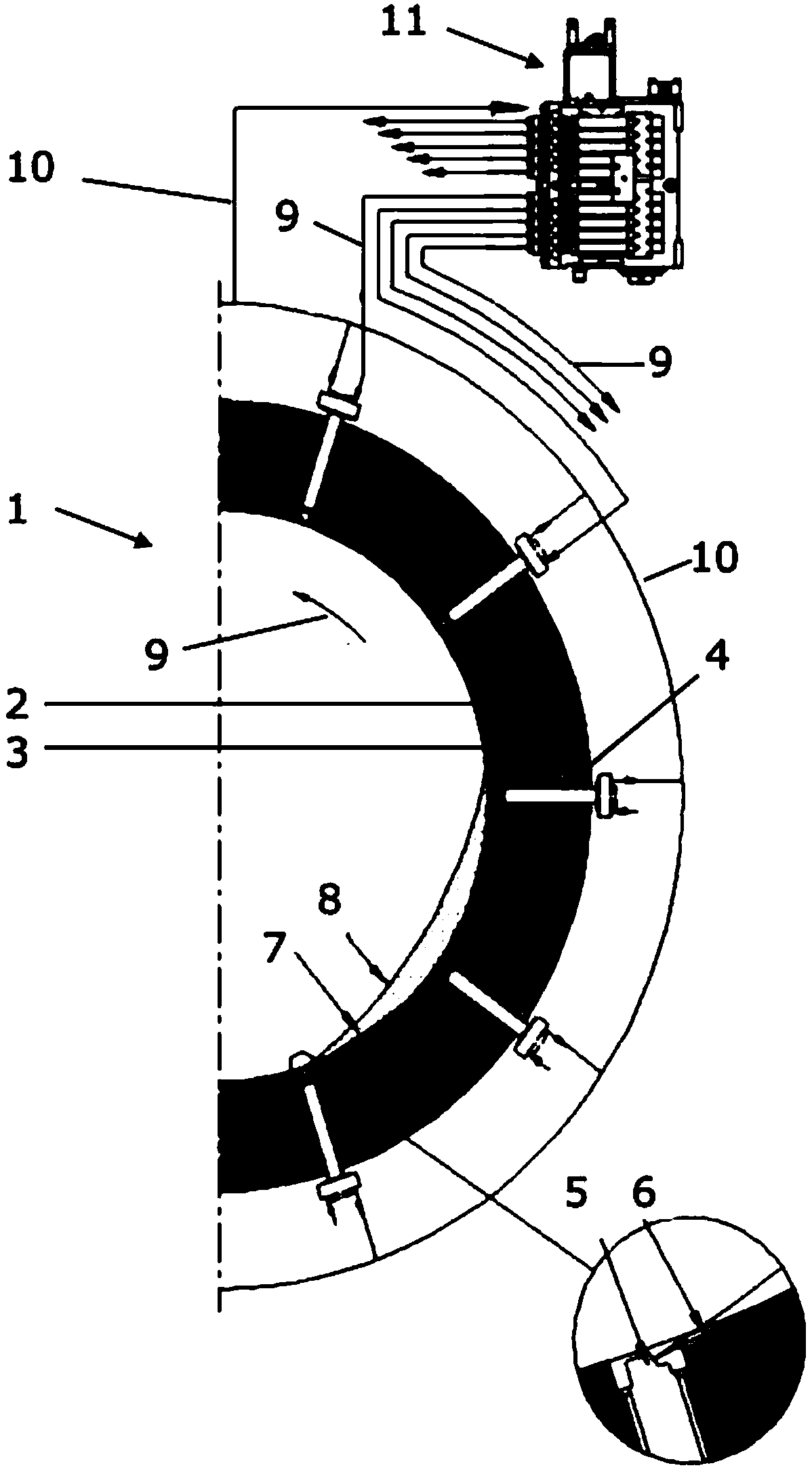
[0031] figure 1 Shown is one half of a cylinder of a large low-speed two-stroke engine, such as a marine diesel engine. The cylinder comprises a cylinder liner 2 arranged inside a cylinder wall 3 . Inside the cylinder wall 3, there are a plurality of lubricating oil injectors 4 distributed along a circle, and the angular distance between adjacent injectors is equal. The injector 4 receives lubricating oil from the lubricating pump and control system 11 through the lubricating supply line 9 . Some lubricating oil is returned to the pump through the lubricating return line 10 . A lubrication pump and control system 11 supplies pressurized lubrication oil to the injector 4 in precisely timed pulses synchronized with the movement of the pistons in the engine 1 . For this synchronization, the lubrication pump and control system 11 includes a computer that monitors the actual state and motion parameters of the engine, including the speed, load and position of the crankshaft, the ...


PUM


Abstract

Injectors for injection of lubrication oil into the cylinder of a large slow-running two-stroke engine, especially marine diesel engine, proved better uniform performance the when using hardened surfaces for the plain bearing in which the valve member slides. Also, hardened surfaces for valve seats at the nozzle was an improvement.

Description

technical field [0001] The present invention relates to an injector for injecting lubricating oil into the cylinders of large low speed two-stroke engines, such as marine diesel engines or gas or diesel engines in powerplants. It also relates to a production method and such an engine. Background technique [0002] For the lubrication of large low-speed two-stroke marine diesel engines, different systems exist, including direct injection of oil into the cylinder liners and / or piston surfaces. Another method, known commercially as the Swirl Injection Principle (SIP), is based on injecting an atomized spray of lubricant into a vortex of purge air in the cylinder. The eddy currents cause the lubricant to be pressed outward against the cylinder walls in a thin uniform layer. In all cases, the timing of lubricant injection is critical. A lube oil injection valve, also known as a lube oil injector, is a one-way valve that includes a syringe housing within which a reciprocating v...

Claims


Application Information

Patent Timeline
Patent Type & Authority Applications(China)
IPC IPC(8): F01M1/08F02M63/00
CPCF01M1/08F02M63/004F02M63/0071F02M2200/9038F02M2200/9053F02M2200/02F02M61/166F01M2001/083
Inventor 拉斯穆斯·汉斯·延森
Owner HANS JENSEN LUBRICATORS
Why Eureka
Try Eureka