Continuous vacuum defoaming device

A technology of vacuum defoaming and feed inlet, which is applied in the direction of liquid degassing, foam dispersion/prevention, chemical instruments and methods, etc., and can solve problems such as efficiency and quality that need to be improved

Inactive Publication Date: 2018-04-06
南充盛达鸿科技有限公司
View PDF2 Cites 3 Cited by
  • Summary
  • Abstract
  • Description
  • Claims
  • Application Information

AI Technical Summary

Problems solved by technology

But efficiency and quality still need to be improved

Method used


Image

  • Continuous vacuum defoaming device
  • Continuous vacuum defoaming device
  • Continuous vacuum defoaming device

Examples


Embodiment 1

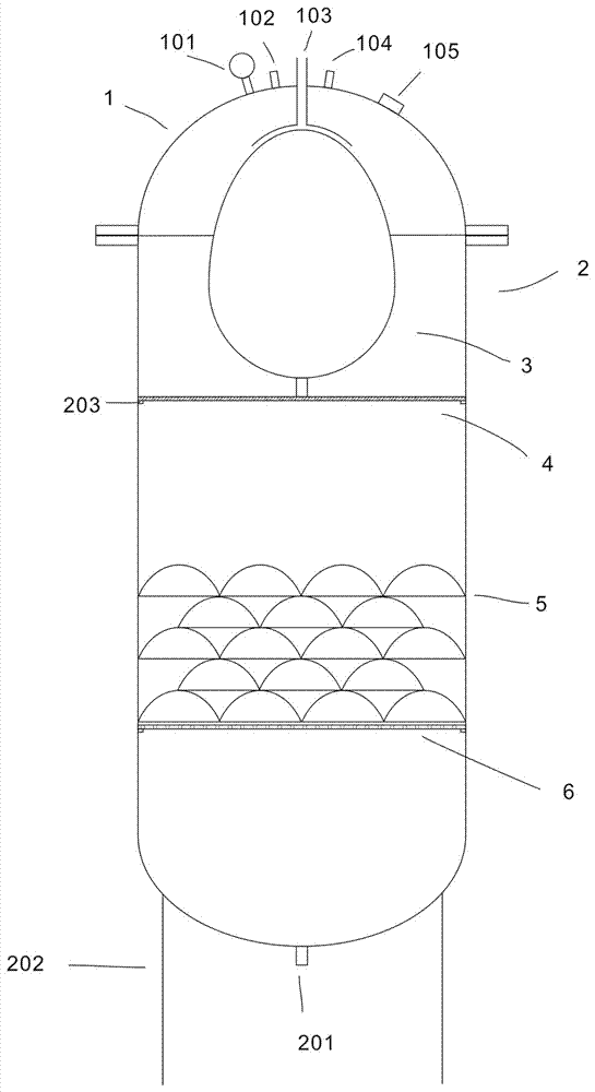
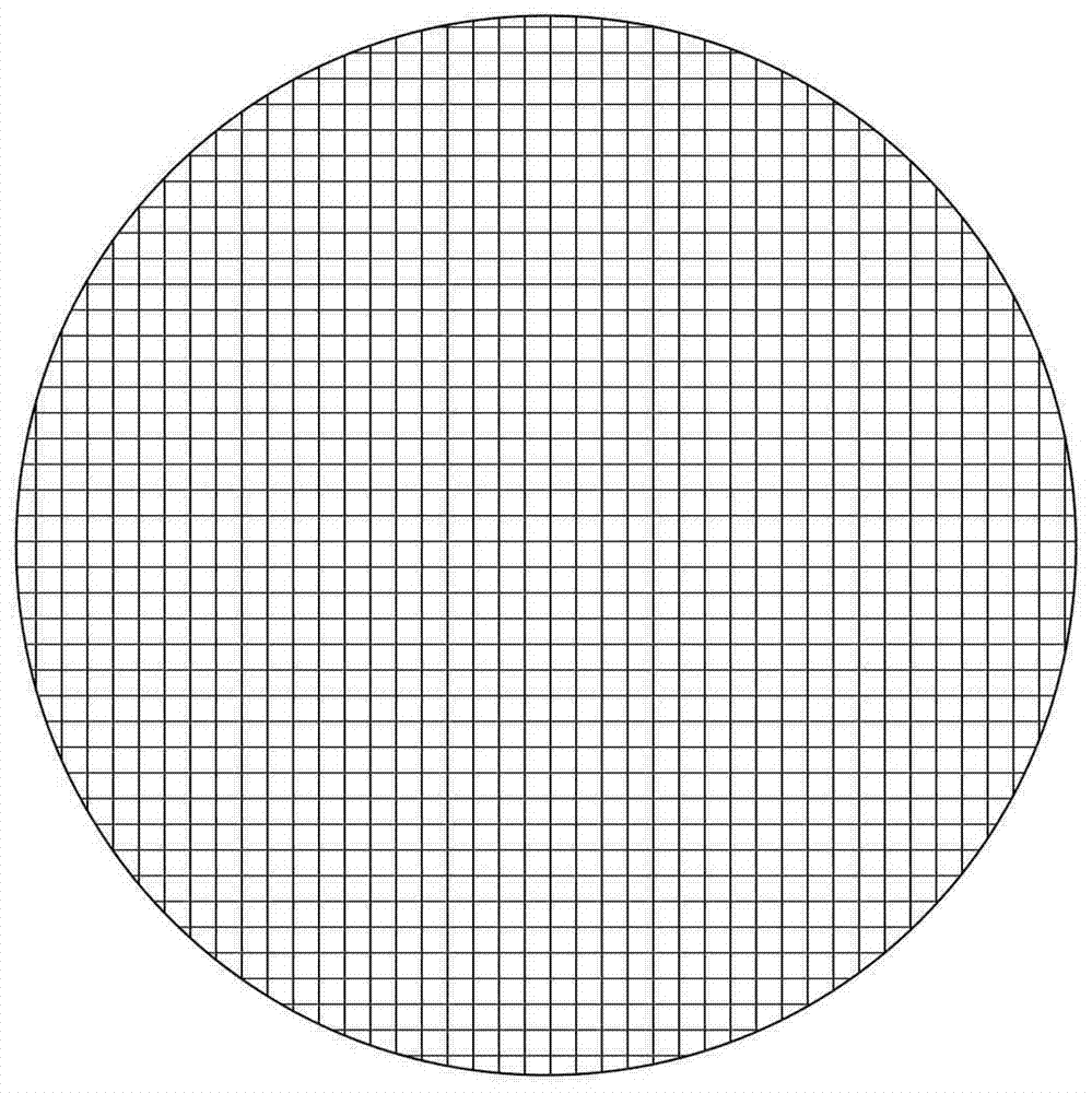
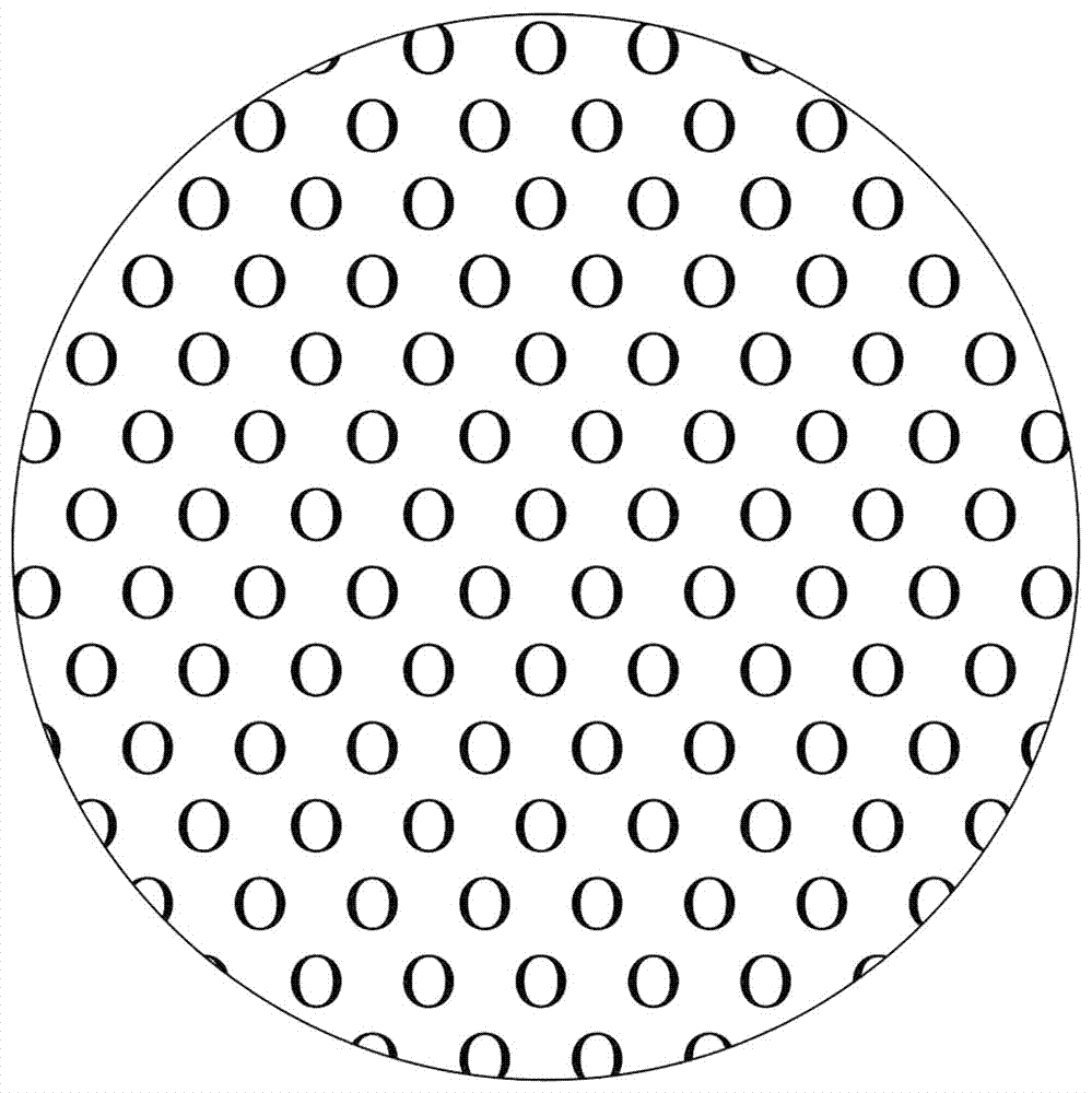
[0014] Embodiment 1, see appendix figure 1 , attached figure 2 , attached image 3 , attached Figure 4 , attached Figure 5 , a continuous vacuum degassing device, comprising a head 1, an air inlet 102, a feed port 103, an air extraction port 104, a barrel body 2, a discharge port 201, a sight glass 105, a vacuum gauge 101, a frame 202, a barrel The upper and lower half sections in the body are fixed with a stopper 203, a screen 4 is placed on the upper stopper, an oval guide body 3 is connected on the screen, and an orifice 6 is placed on the lower stopper in the barrel body. There are several to dozens of umbrella-shaped screens 5 with the convex surface facing upwards stacked, and the discharge end of the feed port is an umbrella-shaped, and a certain gap is maintained with the surface of the oval-shaped guide body.

[0015] The gap between the discharge end of the feed inlet and the surface of the oval guide body is 1-10mm.

[0016] The hole diameter of said orifice...


PUM

PropertyMeasurementUnit
pore sizeaaaaaaaaaa

Abstract

The invention discloses a continuous vacuum defoaming device. The device comprises a seal head 1, a gas inlet 102, a material inlet 103, a gas exhaust port 104, a barrel body 2, a material outlet 201,a sight glass 105, a vacuum gauge 101 and a machine rack 201, and is characterized in that baffle blocks 203 are fixed to both the upper half segment and the lower half segment of the interior of thebarrel body, a screen mesh 4 is placed on the upper baffle block, an oval flow guiding body 3 is connected to the screen mesh, a pore plate 6 is placed on the lower baffle block in the barrel body, several to tens of umbrella-shaped screen meshes 5 with the convex surfaces upward are stacked on the pore plate, the material outlet end of the material inlet is in an umbrella shape, and a certain gap is maintained between the material outlet end of the material inlet and the surface of the oval flow guiding body. The gap between the material outlet end of the material inlet and the surface of the oval flow guiding body is 1-10 mm. The pore diameter of the pore plate is 0.5-10 mm. The purposes are completely achieved that the continuous vacuum defoaming device is simple in structure, flexibleand convenient, convenient to clean, high in defoaming efficiency, low in vacuum requirement and unlikely to cause waste.

Description

technical field [0001] The invention relates to a vacuum device, in particular to a continuous vacuum degassing device. Background technique [0002] As we all know, defoaming is of paramount importance in the chemical industry. The defoaming quality and its effect directly determine the smoothness of production and the quality of products. In the fine chemical industry, many surfactants, inks, coatings and other products need to be defoamed, and in the chemical fiber industry, defoaming is also a necessary process. Especially in the field of man-made fibers. In the traditional viscose fiber production process, the static degassing method is generally used for vacuum degassing. However, this is too long and time-consuming, requiring nearly 30 hours, which is very unfavorable for university production. In the later period, some manufacturers introduced continuous defoaming devices, generally using thin-film method, trickle method, and centrifugation method. But efficienc...

Claims


Application Information

Patent Timeline
Patent Type & Authority Applications(China)
IPC IPC(8): B01D19/02
CPCB01D19/02B01D19/0021
Inventor 任长秋贾宝泉左杨芳
Owner 南充盛达鸿科技有限公司
Why Eureka
Try Eureka