Air-flotation swirling flow contactor and air-flotation swirling flow system
A contactor and flow system technology, applied in chemical instruments and methods, flotation water/sewage treatment, water/sewage multi-stage treatment, etc., can solve problems affecting process flow, low efficiency, pollution, etc., and achieve large treatment flow , increase the processing capacity, and improve the separation effect
- Summary
- Abstract
- Description
- Claims
- Application Information
AI Technical Summary
Problems solved by technology
Method used
Image
Examples
Embodiment 1
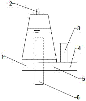
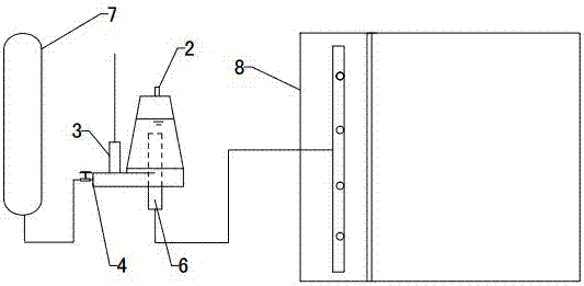
[0025] Refer to attached figure 1 : Air flotation cyclone contactor, including a conical cylinder 1, the side wall of the conical cylinder 1 is connected with a tangentially arranged liquid inlet pipe 5, the top of the conical cylinder 1 is provided with an exhaust port 2, and the bottom is provided with a liquid outlet pipe 6. The outer end of the liquid inlet pipe 5 is provided with two branch pipes.
[0026] The conical cylinder 1 has a narrow top and a wide bottom, and the liquid inlet pipe 5 is arranged on one side of the lower part of the conical cylinder 1 . The top of the cone 1 is provided with an exhaust cavity, and the top of the exhaust cavity is connected to the exhaust port 2 . The liquid outlet pipe 6 is arranged concentrically with the conical cylinder 1, the top of the liquid outlet pipe 6 extends into the inside of the conical cylinder 1, and the top of the liquid outlet pipe 6 is arranged on the top of the conical cylinder 1, and the top of the liquid outle...
Embodiment 2
[0034] The liquid outlet pipe 6 is concentrically arranged with the conical cylinder 1 , the upper part of the liquid outlet pipe 6 extends into the inside of the conical cylinder 1 , and the top of the liquid outlet pipe 6 is arranged at the bottom of the conical cylinder 1 . The top of the liquid outlet pipe 6 is set at the lower part of the conical cylinder 1. Compared with the top of the liquid outlet pipe 6, which is set at the upper part of the conical cylinder 1, it can have a longer residence time and avoid bubble-suspension polymerization. The material moves to the outer wall of the liquid outlet pipe 6 under the action of centrifugal force, but cannot leave the inner cavity of the cyclone contactor. Other settings and working principles are the same as in Embodiment 1.
Embodiment 3
[0036] The liquid inlet pipe 5 is arranged on one side of the middle part of the tapered cylinder 1 . The liquid inlet pipe 5 is set on one side of the middle of the conical cylinder 1, so that the liquid flows from top to bottom. This way can increase the residence time of the bubbles in the contactor and increase the concentration of the bubbles in the contactor. Other settings and working principles are the same as in Embodiment 1.
PUM
 Abstract
Description
Claims
Application Information
 - R&D
- Intellectual Property
- Life Sciences
- Materials
- Tech Scout
- Unparalleled Data Quality
- Higher Quality Content
- 60% Fewer Hallucinations
Browse by: Latest US Patents, China's latest patents, Technical Efficacy Thesaurus, Application Domain, Technology Topic, Popular Technical Reports.
© 2025 PatSnap. All rights reserved.Legal|Privacy policy|Modern Slavery Act Transparency Statement|Sitemap|About US| Contact US: help@patsnap.com


