
Vibration damper for a motor vehicle and a method for producing a press fit between a damper inner tube and at least one separating plate

A vibration damper, motor vehicle technology, applied in shock absorbers, vehicle components, liquid shock absorbers, etc., can solve problems such as noise emissions

Active Publication Date: 2018-04-06
THYSSENKRUPP BILSTEIN +1
View PDF10 Cites 3 Cited by
  • Summary
  • Abstract
  • Description
  • Claims
  • Application Information

AI Technical Summary

Problems solved by technology

Often, the components installed for sealing often result in noise emissions, which are usually attributable to relative movement between these components and / or relative to the inner tube

Method used


Image

  • Vibration damper for a motor vehicle and a method for producing a press fit between a damper inner tube and at least one separating plate
  • Vibration damper for a motor vehicle and a method for producing a press fit between a damper inner tube and at least one separating plate

Examples


Embodiment Construction

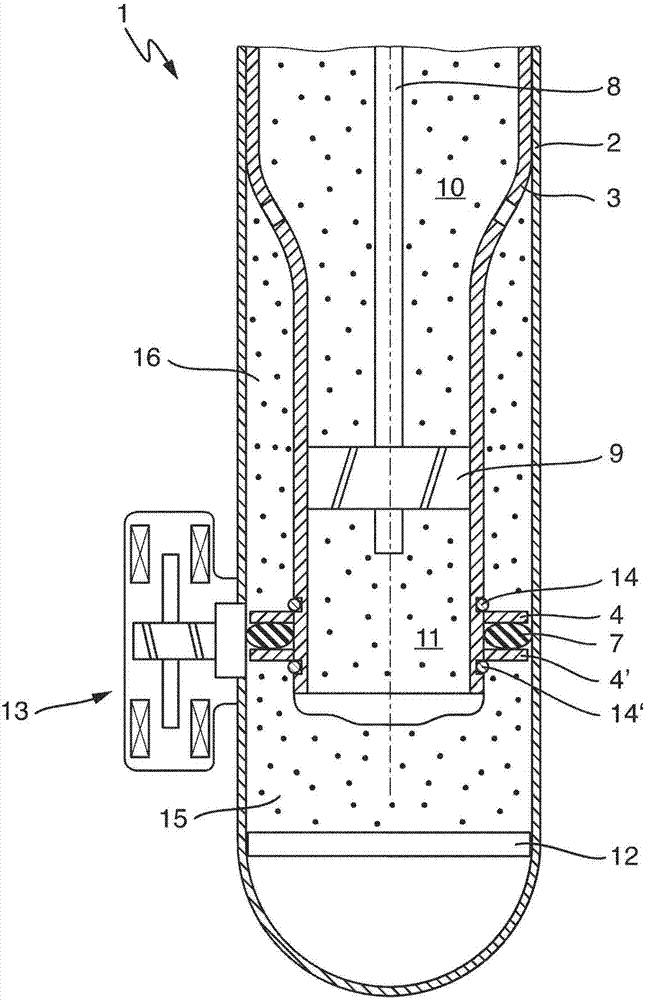
[0035] exist figure 1 , schematically shows a longitudinal section of a vibration damper according to the prior art. The vibration damper 1 has an outer damper tube 2 in which an inner damper tube 3 is arranged. A piston rod 8 capable of reciprocating axial movement is arranged in the damper inner tube 3 , and a working piston 9 is arranged on the piston rod 8 . The working piston 9 separates a working chamber 10 on the piston rod side from a working chamber 11 remote from the piston rod. A release piston 12 is arranged at the end in the damper outer tube 2 . The damper inner tube 3 has at one end a segmentally reduced outer diameter of which the outer diameter of the damper inner tube is reduced. In the region of the segmental reduction of the outer diameter, the two retaining rings 14 , 14 ′ are arranged coaxially in two grooves provided for this purpose on the damper inner tube side of the damper inner tube 3 . In the region between the recesses two separating plates 4 ...


PUM


Abstract

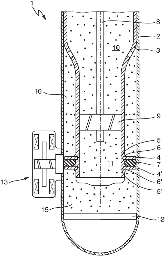
The invention relates to a vibration damper for a motor vehicle and a method for producing a press fit between a damper inner tube and at least one separating plate. A vibration damper 1 may comprisea damper outer tube 2, a damper inner tube 2 having a lateral surface of the damper inner tube and arranged coaxially in the damper outer tube, a separating plate 4, 4' arranged coaxially in a regionof the lateral surface of the damper inner tube, and a sealing element 7 arranged coaxially circumferentially on the damper inner tube on the separating plate. In a region of the separating plate arranged coaxially on the lateral surface of the damper inner tube, a groove 5, 5' for the separating plate may be formed on the lateral surface of the damper inner tube. The separating plate may be arranged in the groove, and the connection between the groove and the separating plate may be press fit, at least in the radial direction.

Description

technical field [0001] The invention relates to a vibration damper for a motor vehicle and a method for producing an interference fit between a damper inner tube and at least one partition plate. Background technique [0002] Vibration dampers for motor vehicles are known in several embodiments from the prior art. Taking the example of a hydraulic vibration damper for a motor vehicle, it comprises a damping cylinder filled with a damping fluid and in which a damping piston connected to a piston rod slides, the damping piston being provided with a pressure-controlled throttle valve and The damping cylinder is divided into two working chambers, and a bypass channel for adjusting the damping force is provided in the damping cylinder, the flow cross section of the bypass channel can be arranged outside the vibration damper and accommodated in the tubular valve housing bypass valve system control. In this damper, the outer tube is formed in a cylindrical shape similarly to the ...

Claims


Application Information

Patent Timeline
Patent Type & Authority Applications(China)
IPC IPC(8): F16F9/16F16F9/36F16F9/32
CPCF16F9/16F16F9/32F16F9/3214F16F9/36B60G13/08B60G2206/41B60G2206/82092F16F9/3235F16F2226/045F16F9/3257F16F9/185F16F9/3207F16F9/3271F16F2230/00F16F2230/0082F16F2230/02
Inventor 朱朋
Owner THYSSENKRUPP BILSTEIN
Learn More