Device and method for testing surface temperature of sintered material layer

A surface temperature and testing device technology, which is applied to measuring devices, thermometers, and electrical devices, etc., can solve problems such as the decline in the quality of surface sinter, short ignition time at high temperature on the surface of the material layer, and excess energy, so as to improve accuracy and reliability. High performance, improved test accuracy, and convenient operation

Pending Publication Date: 2018-04-06
ANSTEEL GRP MINING CO LTD
View PDF9 Cites 3 Cited by
  • Summary
  • Abstract
  • Description
  • Claims
  • Application Information

AI Technical Summary

Problems solved by technology

During the sintering process, due to defects in process parameters and control methods, the high-temperature ignition time on the surface of the material layer is likely to be short, and the heat of the surface layer is quickly transferred downwards under the action of the wind box, which easily causes the sinter on the surface to be brittle, resulting in a decrease in the quality of the sinter on the surface. However, due to the heat storage effect of the thick material layer, the bottom of the material layer is prone to excess energy, resulting in overburning of the sinter. Therefore, it is necessary to find a suitable method for the ignition process to match the thickness of the material layer to meet the needs of ignition and improve the quality of the surface layer of sinter. , which is also an effective way to increase sintering productivity and reduce comprehensi...

Method used


Image

  • Device and method for testing surface temperature of sintered material layer
  • Device and method for testing surface temperature of sintered material layer
  • Device and method for testing surface temperature of sintered material layer

Examples


Embodiment Construction

[0014] The present invention will be further described below in conjunction with accompanying drawing.

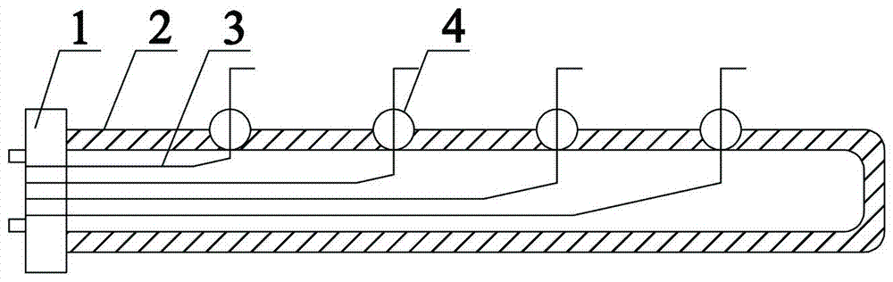
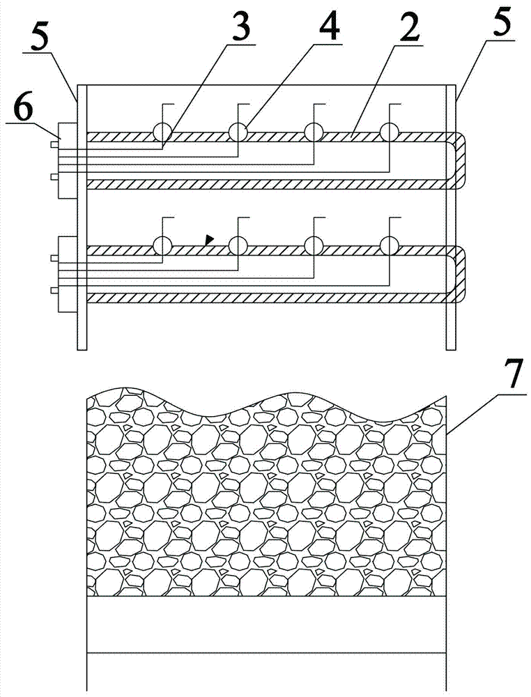
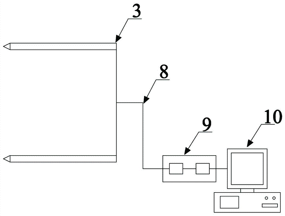
[0015] Such as figure 1 with figure 2 As shown, a test device for the surface temperature of a sintered layer of the present invention includes a temperature data acquisition system 9 and a data processing system 10 installed on the outside of the sintering furnace, and is characterized in that: it also includes The U-shaped casing 2 on the side plate 5 has more than three temperature measuring holes 4 on the U-shaped casing 2, and multiple measuring holes corresponding to the temperature measuring holes 4 are arranged in the U-shaped casing 2. The thermocouple 3 forms a thermocouple group, and the terminals of each temperature-measuring thermocouple 3 are connected to the terminal 6, and the terminal 6 is connected to the temperature data acquisition system 9 installed on the outside of the sintering ignition furnace through a compensation wire 8 and A comprehensive dat...


PUM


Abstract

The invention relates to a device and a method for testing the surface temperature of a sintered material layer. The device comprises a temperature data acquisition and data processing system installed on the outer side of a sintering ignition furnace. The system is characterized by further comprising a U-shaped sleeve. More than three temperature measuring holes are formed in the U-shaped sleeve.A plurality of temperature measuring thermocouples corresponding to the temperature measuring holes are arranged in the U-shaped sleeve so as to form a thermocouple set. The wiring end of each temperature measuring thermocouple is connected with a wiring terminal. All wiring terminals are electrically connected with the temperature data acquisition and data processing system installed on the outer side of the sintering ignition furnace through compensation wires. The test device is adopted by the test method. When the test is finished, temperature data obtained by the plurality of temperaturemeasuring thermocouples are transmitted to a comprehensive data analysis system, and then a result of the temperature difference between different transverse parts is calculated. After that, the result is compared with a data result during normal production, and the ignition is considered to be uniform when the temperature difference is within the range of +/-100 DEG C. Otherwise, the ignition isnot uniform. The device is simple in structure and convenient to operate.

Description

technical field [0001] The invention relates to the technical field of sintering temperature testing, in particular to a testing device and method for the surface temperature of a sintering material layer. Background technique [0002] Increasing the thickness of the material layer in the sintering process is conducive to increasing the output of sintering ore. At the same time, with the increase of the material layer thickness, it is conducive to heat storage in the sintering process, so that the heat in the lower part of the material layer is more abundant, so that the consumption of solid fuel in the sintering process decreases, and the sintering yield and Firing rate increased. During the sintering process, due to defects in process parameters and control methods, the high-temperature ignition time on the surface of the material layer is likely to be short, and the heat of the surface layer is quickly transferred downwards under the action of the wind box, which easily c...

Claims


Application Information

Patent Timeline
IPC IPC(8): G01K7/02G01K7/10
CPCG01K7/023G01K7/10
Inventor 王林杨光何志军
Owner ANSTEEL GRP MINING CO LTD
Why Eureka
Try Eureka