Optimization method and optimization apparatus for powertrain mounting system

A technology for mounting systems and powertrains, applied in the field of optimization methods and optimization devices for powertrain mounting systems, can solve problems such as inability to take into account the modal frequency distribution, shorten robustness analysis and debugging cycles, and shorten development Cycle, the effect of improving efficiency

Active Publication Date: 2018-04-06
GREAT WALL MOTOR CO LTD
View PDF5 Cites 14 Cited by
  • Summary
  • Abstract
  • Description
  • Claims
  • Application Information

AI Technical Summary

Problems solved by technology

[0008] In view of this, the present invention aims to propose an optimization method for the powertrain mount system to solve the problem that the existing method cannot take into account the modal frequency distribution due to the optimization of the decoupling rate

Method used


Image

  • Optimization method and optimization apparatus for powertrain mounting system
  • Optimization method and optimization apparatus for powertrain mounting system
  • Optimization method and optimization apparatus for powertrain mounting system

Examples


Embodiment 1

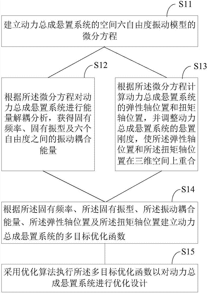
[0060] The embodiment of the present invention provides a method for optimizing the powertrain suspension system, such as figure 1 As shown, the optimization method of the powertrain suspension system mainly includes the following steps:

[0061] Step S11, establishing a differential equation of a space six-degree-of-freedom vibration model of the powertrain mount system.

[0062] The natural modal frequency of the powertrain mount system is generally below 20Hz, and the lowest-order elastic body modal frequency of the powertrain is generally above 150Hz, so that the powertrain and the body can be regarded as rigid bodies, and the powertrain mount system Simplified to a rigid body six degrees of freedom vibration system.

[0063] Accordingly, this embodiment establishes a powertrain center-of-mass coordinate system for a rigid body six-degree-of-freedom vibration system. In this coordinate system, the X-axis is parallel to the engine crankshaft and points to the front end of ...

Embodiment 2

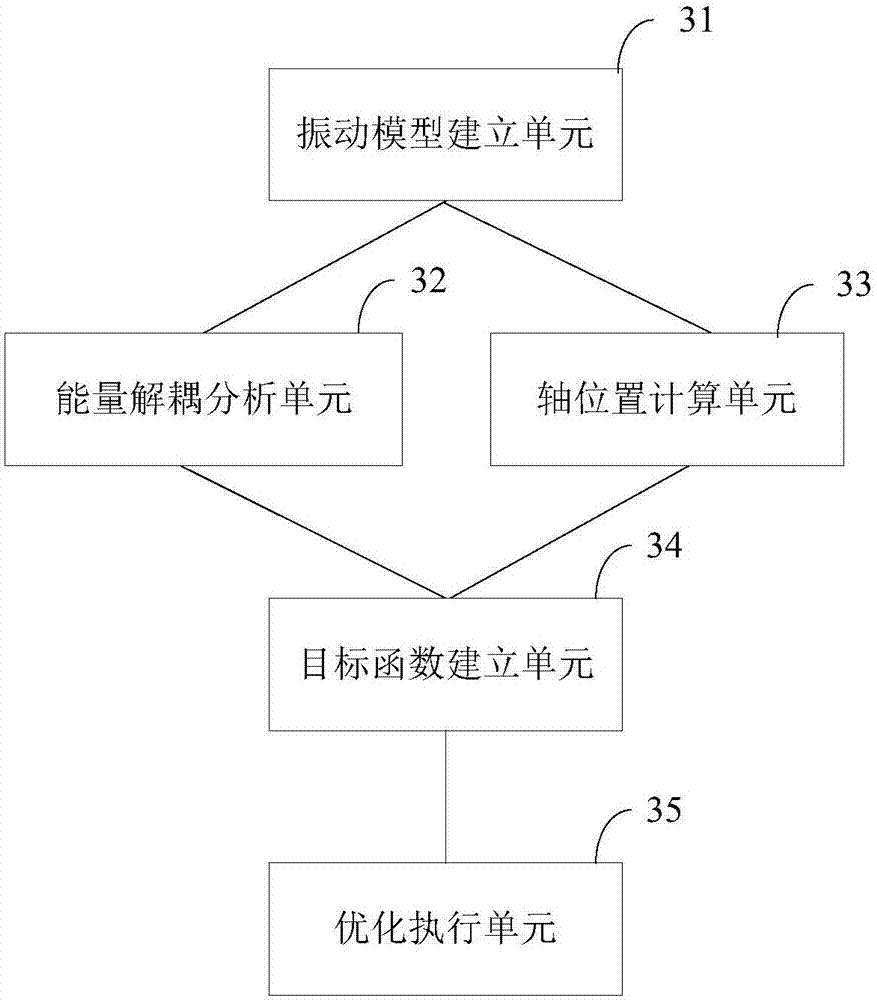
[0119] Based on the same inventive idea as the optimization device for the powertrain mount system in the first embodiment above, this embodiment provides an optimization device for the powertrain mount system, such as image 3 As shown, the optimization device of the powertrain mount system includes: a vibration model establishment unit 31, which is used to establish the differential equation of the space six-degree-of-freedom vibration model of the powertrain mount system; an energy decoupling analysis unit 32, which uses Perform energy decoupling analysis on the powertrain mount system according to the differential equation to obtain the natural frequency, natural mode shape and vibration coupling energy among the six degrees of freedom; the shaft position calculation unit 33 is used to The equation calculates the position of the elastic axis and the position of the torque axis of the powertrain mount system, and adjusts the mount stiffness of the powertrain mount system so ...


PUM


Abstract

The invention relates to the field of engines and provides an optimization method and an optimization apparatus for a powertrain mounting system. The optimization method comprises the steps of building a differential equation of a spatial six-degree-of-freedom vibration model of the powertrain mounting system; according to the differential equation, performing energy decoupling analysis on the powertrain mounting system to obtain an inherent frequency, a natural vibration mode and vibration coupling energy among six degrees of freedom; according to the differential equation, calculating an elastic axis position and a torque axis position of the powertrain mounting system, and adjusting the mounting stiffness of the powertrain mounting system to enable the elastic axis position and the torque axis position to be coincided in a three-dimensional space; according to the inherent frequency, the natural vibration mode, the vibration coupling energy, the elastic axis position and the torqueaxis position, building a multi-objective optimization function of the powertrain mounting system; and by adopting an optimization algorithm, executing the multi-objective optimization function to perform optimization design on the powertrain mounting system. The problem of incapability of considering mode frequency distribution due to decoupling rate optimization is effectively solved.

Description

technical field [0001] The invention relates to the field of engines, in particular to an optimization method and an optimization device for a powertrain suspension system. Background technique [0002] The design of the mount system is a complex system problem, which involves the optimization of the robustness of the design input parameters, the limitation of the mount stiffness and spatial position, and the vibro-acoustic characteristics of the vehicle. At present, the optimization scheme of the mount system is generally based on the energy decoupling method, that is, the arrangement position of the mount and the stiffness of the mount are used as design variables, and the decoupling rate is taken as the primary optimization goal. The design status of frequency decoupling is better. [0003] However, the existing optimization method with the decoupling rate as the primary optimization goal has the following defects: [0004] 1) The existing method takes improving the dec...

Claims


Application Information

Patent Timeline
Patent Type & Authority Applications(China)
IPC IPC(8): G06F17/50
CPCG06F30/15G06F30/20Y02T90/00
Inventor 鲍金龙石岩连俊义白炜赵珂
Owner GREAT WALL MOTOR CO LTD
Why Eureka
Try Eureka