Eureka AIR delivers breakthrough ideas for toughest innovation challenges, trusted by R&D personnel around the world.

Multi-microgrid flexible interconnection structure based on common connection units

A technology of public connection and interconnection structure, applied in the field of power grid, can solve the problems that the networking devices cannot be realized at the same time, and the lack of asynchronous interconnection

Active Publication Date: 2018-04-06
SHANGHAI JIAO TONG UNIV
View PDF9 Cites 3 Cited by
  • Summary
  • Abstract
  • Description
  • Claims
  • Application Information

AI Technical Summary

Problems solved by technology

[0004] The present invention aims at the defects that the existing networking device cannot simultaneously realize the direct interconnection of microgrids of different voltage levels, the hybrid interconnection of AC microgrids and DC microgrids, the asynchronous interconnection of multiple microgrids, and the lack of coordination control devices, and proposes a public-based The multi-microgrid flexible interconnection structure of the connection unit can improve the operation reliability of the multi-microgrid system through the frequency, voltage and power support of the public grid, and can provide higher control dimensions and more variable control strategies, thereby obtaining more Good control effect improves the operating flexibility of the multi-microgrid system, reduces the electromagnetic coupling between microgrids, improves power quality, and improves the access capability and utilization rate of distributed new energy

Method used


Image

  • Multi-microgrid flexible interconnection structure based on common connection units
  • Multi-microgrid flexible interconnection structure based on common connection units
  • Multi-microgrid flexible interconnection structure based on common connection units

Examples


Embodiment Construction

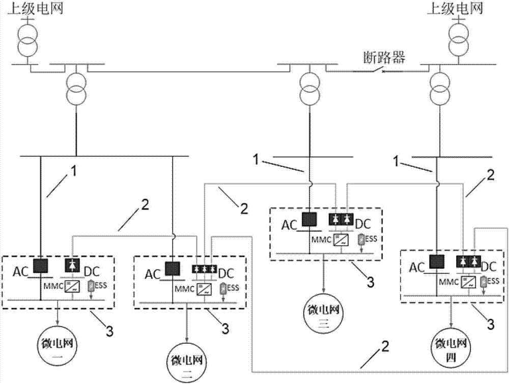
[0013] like figure 1 As shown, this embodiment includes: several AC interface connection lines 1, several DC interface connection lines 2 and several public connection units 3, wherein: the AC interface connection lines 1 are connected to the upper-level power grid, that is, the public power grid and the public connection unit 3, and the DC interface The connection line 2 is connected to the public connection unit 3 to which it belongs and other public connection units 3 , and each of the public connection units 3 is connected to its corresponding microgrid.

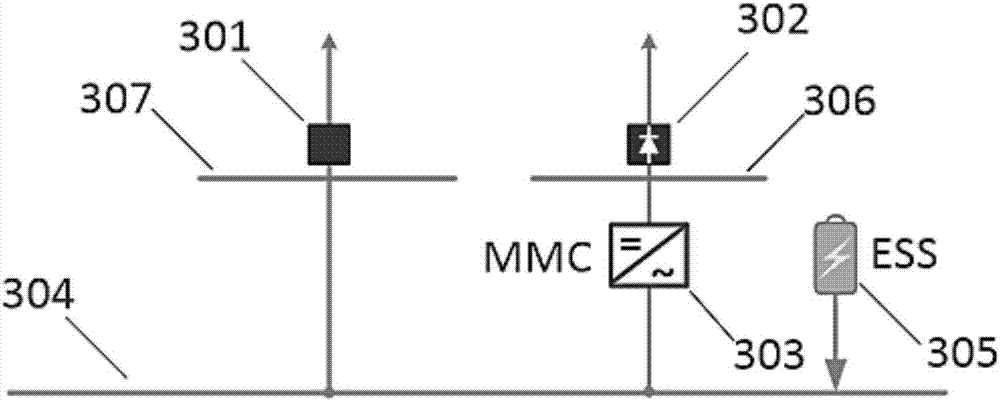
[0014] like figure 2 As shown, the public connection unit 3 includes: AC circuit breaker 301, DC circuit breaker 302, modular multilevel converter 303, DC connection bus 306, AC connection bus 307 and public connection bus 304, wherein: AC The two ends of the circuit breaker 301 are respectively connected to the AC interface connection line 1 and the AC connection bus bar 307, the two ends of the DC circuit breaker 302...


PUM


Abstract

A multi-microgrid flexible interconnection structure based on common connection units comprises a plurality of alternating current interface connection lines, a plurality of direct current interface connection lines and a plurality of common connection units; two ends of each alternating current interface connection line are respectively connected with a public supply network and one correspondingcommon connection unit; two ends of each direct current interface connection line are respectively connected with the common connection units; and each common connection unit is connected with one corresponding microgrid. The multi-microgrid flexible interconnection structure based on common connection units can improve the operation reliability of the multi-microgrid system by support of the frequency, the voltage and the power of the public supply network and can provide a higher control dimension and more flexible control strategy so as to obtain a better control effect, improve operationflexibility of the multi-microgrid system, reduce the electromagnetic coupling between the microgrids, improve the electric energy quality and improve the access capacity and the utilization rate of distributed new energy.

Description

technical field [0001] The invention relates to a technology in the field of power grids, in particular to a multi-micro-grid flexible interconnection structure based on a common connection unit for fast and flexible connection of multiple sub-micro-grids. Background technique [0002] The environmental problems caused by fossil fuels have drawn worldwide attention to renewable energy such as wind power and solar power. In addition, the rapid development of related technologies such as power electronic devices and microgrids has also promoted the widespread application of renewable energy. In order to realize the coordinated control of distributed power and provide clean and efficient power to the grid, microgrid has become an effective way to accommodate multiple types of distributed power. Different from the traditional distribution network, the microgrid has two modes of operation, grid-connected and isolated, and has good operational flexibility and reliability. However...

Claims


Application Information

Patent Timeline
IPC IPC(8): H02J4/00
CPCH02J4/00
Inventor 吴攀黄文焘邰能灵郑晓冬
Owner SHANGHAI JIAO TONG UNIV
Why Eureka
Eureka Blog
Learn More