Automatic detection device and method of body surface quality loss and vehicular intelligent detection system
An automatic detection and vehicle technology, which is applied in the field of vehicle intelligent detection system, automatic detection equipment for body surface quality damage, automatic detection of body surface quality damage, and automobile inspection equipment, can solve problems such as time-consuming, labor-intensive, missing quality defects, and high labor intensity.
- Summary
- Abstract
- Description
- Claims
- Application Information
AI Technical Summary
Problems solved by technology
Method used
Image
Examples
Embodiment 1
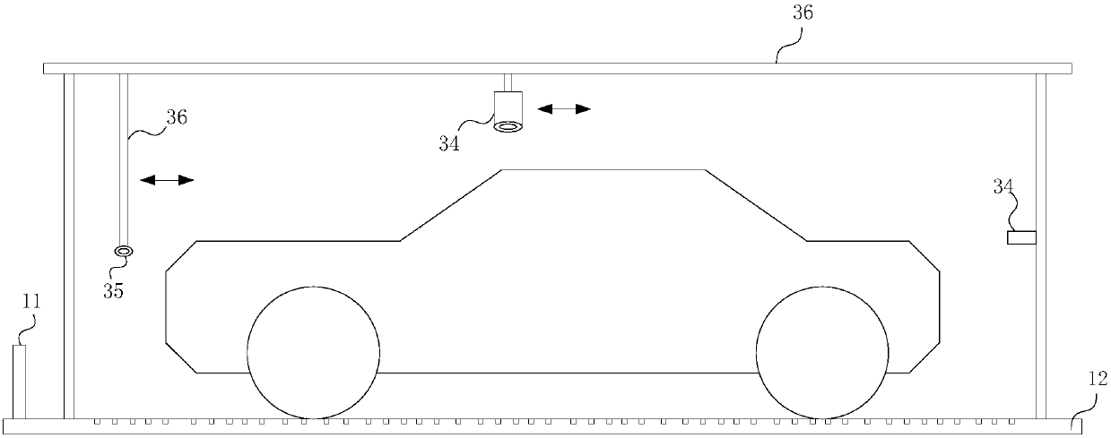
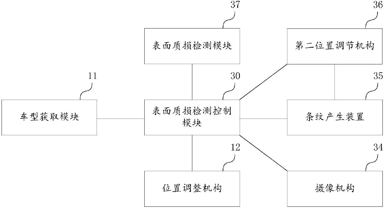
[0067] see figure 1 , figure 2 , the present invention discloses an automatic detection device for surface quality damage of a vehicle body. The automatic detection device for surface quality damage of a vehicle body includes: a vehicle type acquisition module 11, a vehicle position acquisition unit, a position adjustment mechanism 12, a camera mechanism 34, a streak generation device 35, a Two position adjustment mechanism 36 , surface quality damage detection module 37 , surface quality damage detection control module 30 .
[0068] The vehicle type acquisition module 11 is used to identify the vehicle model; the vehicle type acquisition module includes an RFID identifier, and the unique identification code of the vehicle is identified by the RFID identifier to obtain vehicle information.
[0069] The position obtaining unit is used to obtain the position information of the vehicle, and judge whether the position is a set position; if not, adjust the position of the vehicle...
Embodiment 2
[0085] An automatic detection device for surface quality damage of a vehicle body, the automatic detection device for surface quality damage of a vehicle body includes: a camera mechanism, a streak generating device, a second position adjustment mechanism, a detection module, and a control system;
[0086] The control system is connected to the streak generating device, and the streak generating device is controlled to generate moiré fringes in a set area on the surface of the vehicle body;
[0087] The control system is connected to the second position adjustment mechanism, and the second position adjustment mechanism controls the movement of the stripe generating device; thus, the moiré fringe moves on the surface of the vehicle body; during the movement of the stripes, the image data of the corresponding vehicle surface is obtained by the camera mechanism;
[0088] The detection module searches for comparison image data from the database according to the vehicle model; compa...
Embodiment 3
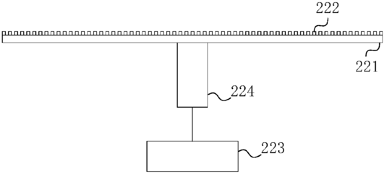
[0094] The difference between this embodiment and Embodiment 1 is that in this embodiment, please refer to image 3 , the position adjustment mechanism 12 includes a load plate 221 for carrying the vehicle, a plurality of first distance sensors 222 distributed on the load plate, a load plate adjustment calculation module 223 , and a load plate adjustment mechanism 224 .
[0095] The load plate adjustment calculation module 223 includes a vehicle parking position acquisition unit and an adjustment calculation unit.
[0096] The vehicle parking position obtaining unit is used to obtain the parking position of the vehicle according to the plurality of first distance sensors 222 closely arranged on the bearing plate, obtain the specific position distribution of the vehicle edge, and thereby obtain the set key comparison in the vehicle edge The specific coordinates of the point; the key comparison point can include the center position point of the front end of the vehicle and the c...
PUM
 Abstract
Description
Claims
Application Information
 - R&D
- Intellectual Property
- Life Sciences
- Materials
- Tech Scout
- Unparalleled Data Quality
- Higher Quality Content
- 60% Fewer Hallucinations
Browse by: Latest US Patents, China's latest patents, Technical Efficacy Thesaurus, Application Domain, Technology Topic, Popular Technical Reports.
© 2025 PatSnap. All rights reserved.Legal|Privacy policy|Modern Slavery Act Transparency Statement|Sitemap|About US| Contact US: help@patsnap.com


