Eureka AIR delivers breakthrough ideas for toughest innovation challenges, trusted by R&D personnel around the world.

In-vitro myocardial perfusion device

A perfusion and heart technology, applied in the field of isolated heart perfusion devices, can solve the problems of pipeline experiment accident, lack, affecting the accuracy of experimental data, etc., and achieve the effect of saving medicinal liquid

Inactive Publication Date: 2018-04-10
孙培培
View PDF0 Cites 6 Cited by
  • Summary
  • Abstract
  • Description
  • Claims
  • Application Information

AI Technical Summary

Problems solved by technology

The two methods have their own advantages and disadvantages and application ranges, and the experimental devices are also different. Regardless of the constant pressure and constant flow perfusion methods, glass tubes are required for constant temperature water circulation in the installation structure. It is necessary to consider the heat loss during the flow process. The longer the pipeline, the faster the heat loss, the longer the insulation path of the constant water bath is required, and the temperature change affects the accuracy of the experimental data. At the same time, the existing constant current and constant pressure The perfusion device lacks a corresponding auxiliary liquid adding device. When the auxiliary operation is performed at the same time as the experiment, the original experimental process needs to be stopped, which affects the accuracy of the experiment, and because there are many steps in the experiment, the complicated pipeline connection is easy to cause experimental accident

Method used


Image

  • In-vitro myocardial perfusion device

Examples


Embodiment

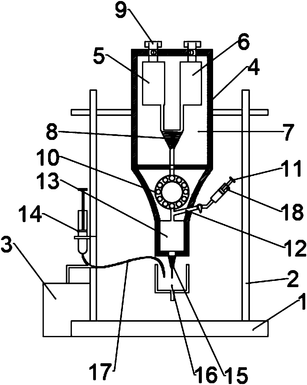
[0018] Such as figure 1 As shown, the present invention provides an isolated heart perfusion device, including a base 1 and a bracket 2, a water bath tube 7 is fixed on the top of the bracket 2, and a K-H liquid bottle 5 and a mixed gas bottle 6 are arranged inside the water bath tube 7 , and the top of the K-H liquid bottle 5 and the mixed gas bottle 6 are provided with a feeding port 9, the bottom of the K-H liquid bottle 5 and the mixed gas bottle 6 is connected with a spiral mixer 8 through a plexiglass tube, and the K-H liquid bottle 5 And the mixed gas bottle 6 is placed in the inside of the water bath tube 7, so that the solution in the bottle and the gas remain well active before mixing again, and the K-H solution and the mixer through the spiral mixer 8 then maintain a good mixing degree, avoiding The mixing degree of the perfusate affects the accuracy of the experiment. A manual ball valve is installed at the mouth of the K-H liquid bottle 5 and the mixed gas bottle ...


PUM


Abstract

The invention discloses an in-vitro myocardial perfusion device which comprises a base and a support. A water bath cylinder is fixed to the top of the support, a K-H liquid bottle and a mixed gas bottle are arranged in the water bath cylinder, charging ports are formed in the top of the K-H liquid bottle and the top of the mixed gas bottle, the bottom of the K-H liquid bottle and the bottom of themixed gas bottle are connected with a spiral mixer through organic glass tubes, the spiral mixer is connected with a peristaltic pump through a glass tube, the bottom of the peristaltic pump is connected with a perfusion liquid cannula, an oblique tube is connected to the glass tube between the peristaltic pump and the perfusion liquid cannula and is connected with a 20 ml injector, a stop screwis arranged on the 20 ml injector, a 20 G liquid dropping head is arranged at the bottom of the perfusion liquid cannula, a perfusion utensil is arranged at the bottom of the 20 G liquid dropping headand is connected with a 100 ml injector through a rubber hose, the 100 ml injector is installed at the left end of the support, and a transducer is arranged on the left side of the base and is connected with the rubber hose through a glass tube.

Description

technical field [0001] The invention relates to the technical field of experimental equipment, in particular to an isolated heart perfusion device. Background technique [0002] Retrograde perfusion of isolated mammalian heart aorta (Langendorff method) is still an important technical method in the field of cardiovascular research, and its content has gradually been extended to transgenic mouse models associated with the cardiovascular system. The Langendorff method has two basic perfusion methods: constant pressure and constant current. The two methods have their own advantages and disadvantages and application ranges, and the experimental devices are also different. Regardless of the constant pressure and constant flow perfusion methods, glass tubes are required for constant temperature water circulation in the installation structure. It is necessary to consider the heat loss during the flow process. The longer the pipeline, the faster the heat loss, the longer the insula...

Claims


Application Information

Patent Timeline
Patent Type & Authority Applications(China)
IPC IPC(8): G01N33/00
CPCG01N33/00
Inventor 孙培培
Owner 孙培培
Why Eureka
Eureka Blog
Learn More