
Three-dimensional laser scanning head

A three-dimensional laser, scanning head technology, applied in optics, optical components, instruments, etc., to achieve the effect of realizing large-scale full-angle scanning, improving motion accuracy and motion speed, and improving scanning speed

Pending Publication Date: 2018-04-10
曾林旺
View PDF1 Cites 2 Cited by
  • Summary
  • Abstract
  • Description
  • Claims
  • Application Information

AI Technical Summary

Problems solved by technology

[0005] Therefore, in view of the above-mentioned technical shortcomings, the present invention has made significant improvements to the original technology through ingenious ideas. The present invention proposes a three-dimensional laser scanning head, designs a planetary gear transmission group, improves the structure, and truly realizes the vertical rotation direction and The independent movement of the horizontal rotation direction simplifies the control of the transmission system, facilitates the operation, improves the movement precision, and overcomes the problem of mistakes caused by inconvenient operation and control in the scheme with the background technology; in addition, the present invention is also provided with a zoom system , the functions that can be realized by the scanning head are increased, and the laser distance sensor is also set to improve the accuracy of the whole system. The full reflection mirror with a larger mirror area can expand the scanning range, and avoid the problem of the transmission system's strength reduction due to the opening of the light hole.

Method used


Image

  • Three-dimensional laser scanning head
  • Three-dimensional laser scanning head
  • Three-dimensional laser scanning head

Examples


Embodiment 1

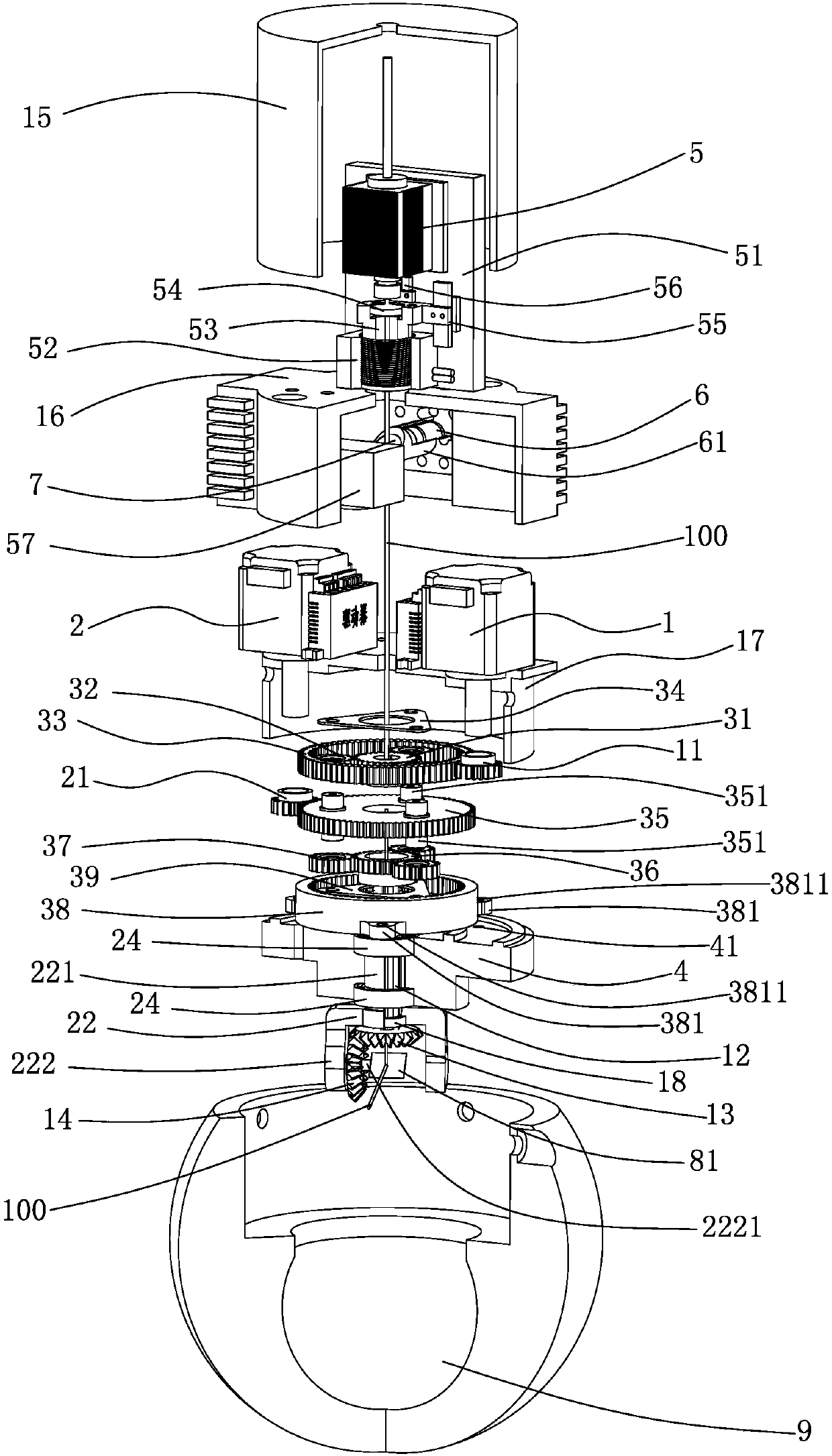
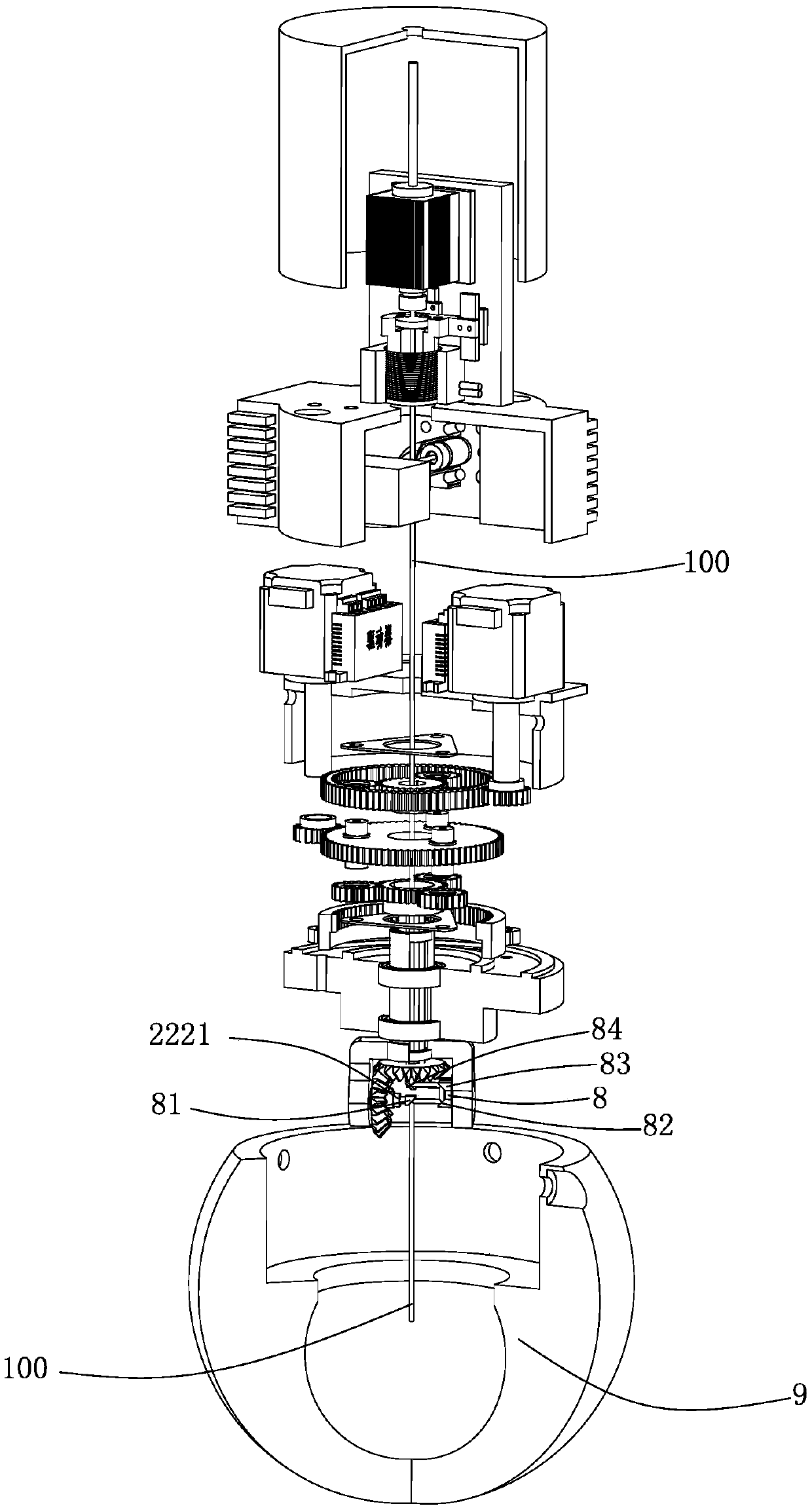
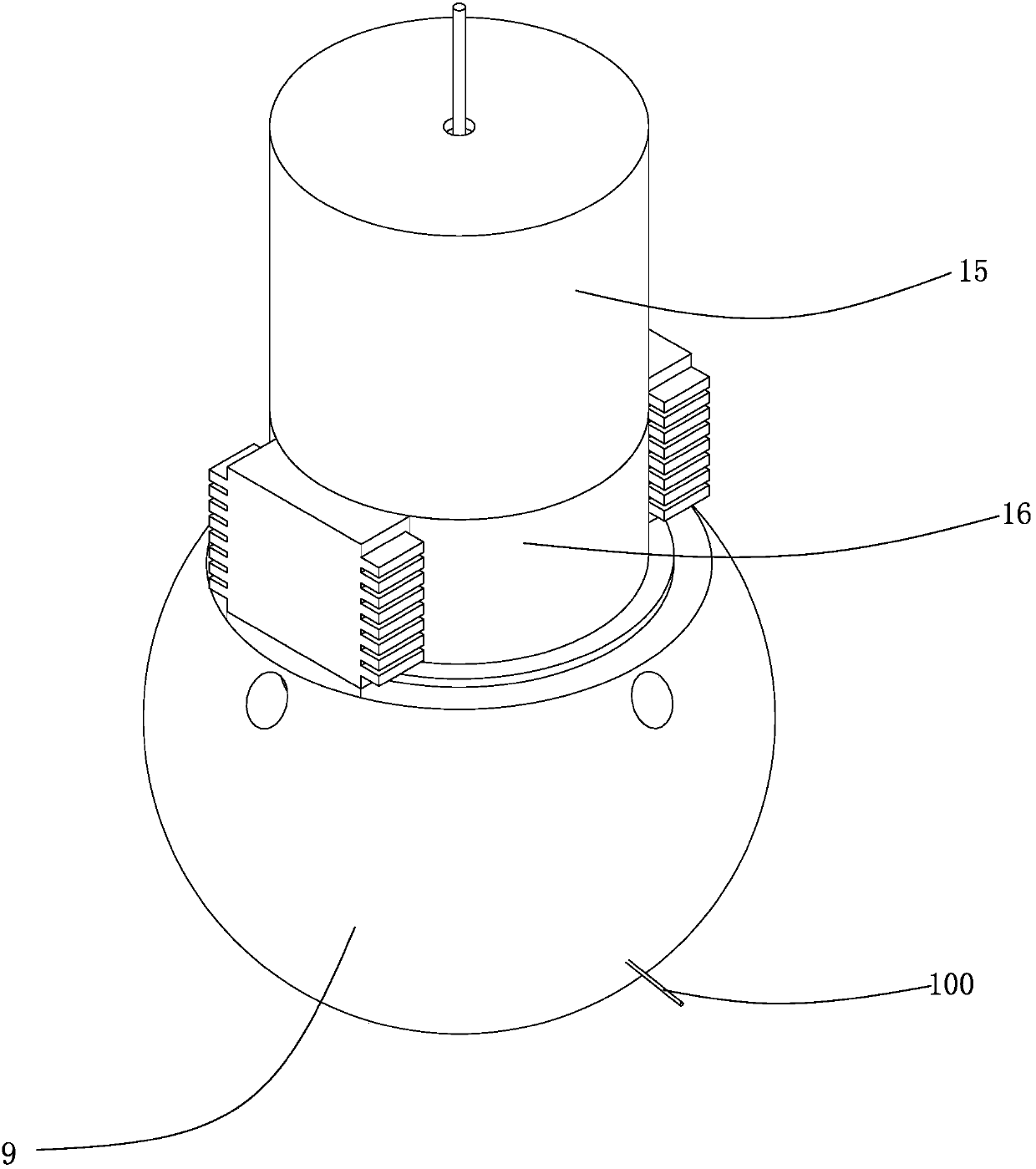
[0030] refer to figure 1 , figure 2 , image 3 , Figure 4 and Figure 8 As shown, a three-dimensional laser scanning head includes an optical path assembly and a drive assembly, and the drive assembly includes a vertical rotation motor 1, a horizontal rotation motor 2, a planetary gear transmission set 3, a horizontal rotation bracket mounting plate 4, a vertical rotation drive Gear 11, horizontal rotation drive gear 21, vertical rotation shaft 12, horizontal rotation bracket 22, vertical rotation driving bevel gear 13 and vertical rotation driven bevel gear 14, the planetary gear transmission set includes a vertical rotation planetary gear ring 33. Vertically rotating sun gear 31, vertically rotating planetary gear 32, vertically rotating planetary gear baffle plate 34, common gear carrier 35, horizontally rotating planetary gear ring gear 38, horizontally rotating planetary gear 37, horizontally rotating sun gear 36 And horizontal rotation planetary gear baffle plate 3...

Embodiment 2

[0046] refer to Figure 5 , Figure 6 , Figure 7 , Figure 8 and Figure 9As shown, a three-dimensional laser scanning head includes an optical path assembly and a drive assembly, and the drive assembly includes a vertical rotation motor 1, a horizontal rotation motor 2, a planetary gear transmission set 3, a horizontal rotation bracket mounting plate 4, a vertical rotation drive Gear 11, horizontal rotation drive gear 21, vertical rotation shaft 12, horizontal rotation bracket 22, vertical rotation driving bevel gear 13 and vertical rotation driven bevel gear 14, the planetary gear transmission set includes a vertical rotation planetary gear ring 33. Vertically rotating sun gear 31, vertically rotating planetary gear 32, vertically rotating planetary gear baffle plate 34, common gear carrier 35, horizontally rotating planetary gear ring gear 38, horizontally rotating planetary gear 37, horizontally rotating sun gear 36 And horizontal rotation planetary gear baffle plate ...


PUM


Abstract

The invention discloses a three-dimensional laser scanning head, and the scanning head comprises an optical path assembly and a drive assembly, wherein the drive assembly includes a planetary gear transmission group, and the optical path assembly comprises a semi-transmission and semi-reflection mirror, a total reflection mirror group and a field lens. The drive assembly can be set at one end of the field lens, thereby enabling the drive assembly to be disposed between the semi-transmission and semi-reflection mirror and the field lens. The drive assembly can be set at the other end of the field lens, thereby enabling the field lens to be disposed between the semi-transmission and semi-reflection mirror and the drive assembly. In addition, several schemes which meet the different scanningdemands are designed for the total reflection mirror group. The scanning head is provided with the planetary gear transmission group, thereby achieving the independent movement in the rotation direction, and simplifying the control of a transmission system. The scanning head is convenient to operate, and improves the movement precision. The invention also provides the other structural layout, thereby enabling the total reflection mirror group to employ a total reflector with the increased mirror surface area so as to enlarge the scanning range. In addition, a variable focal length system and alaser range-finding system are added, thereby enabling the scanning head to have corresponding functions.

Description

technical field [0001] The invention relates to the technical field of laser scanning equipment, in particular to a three-dimensional laser scanning head. Background technique [0002] The existing scanning head adopts the dual vibrating mirror method, that is, one vibrating mirror rotates around the horizontal axis and the other vibrating mirror rotates around the vertical axis without intersecting space. The superimposition of the two vibrating mirrors realizes scanning within a certain area. It is determined by the size of the lens, and the zoom is realized by the field lens. To realize a wide range of scanning, it is necessary to increase the size of the vibrating mirror, that is, the mass of the vibrating mirror is increased, and the required space is increased. A large burden leads to the inability to improve the accuracy and speed of the galvanometer movement, resulting in the inability to improve the scanning accuracy and speed, and it is difficult to expand the scan...

Claims


Application Information

Patent Timeline
IPC IPC(8): G02B26/10G02B26/12
CPCG02B26/105G02B26/121G02B26/127
Inventor 曾林旺
Owner 曾林旺
Learn More