

Lining press fitting device and press fitting method
A press-fitting device and bushing technology, applied in metal processing, metal processing equipment, manufacturing tools, etc., to achieve the effect of improving processing efficiency, moving smoothly, and reducing labor intensity
- Summary
- Abstract
- Description
- Claims
- Application Information
AI Technical Summary
Problems solved by technology
Method used
Image

Examples
Embodiment 1
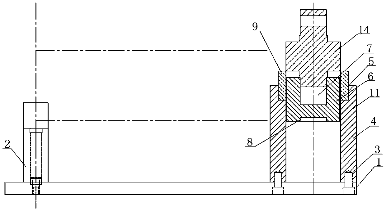
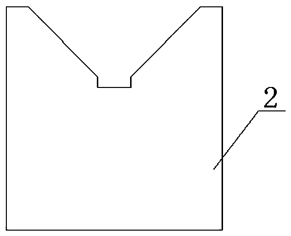
[0027] Such as Figure 2-3 As shown, a bushing press-fitting device includes a base plate 1, wherein a V-shaped block 2 and a base 3 are fixed on the base plate 1 by bolts, and the distance between the V-shaped block 2 and the base 3 matches the length of the workpiece, where V The top of the block 2 is a V-shaped structure, the base 3 is a hollow cylindrical structure, an annular groove 5 is arranged on the inner side of the top of the base 3, a bushing positioning block 6 matching the hollow structure is arranged inside the base 3, and the upper end surface of the bushing positioning block 6 An upper groove 7 and a lower groove 8 are arranged at the center of the lower end face respectively, and the ring 9 is placed in the annular groove 5 .
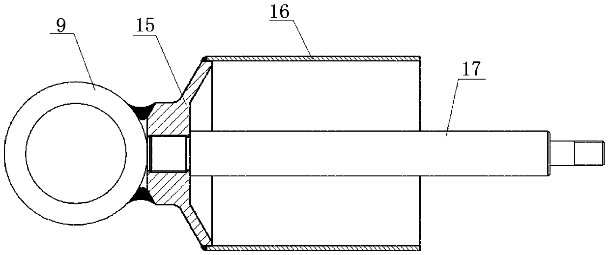
[0028] When using the bushing pressing device of the present invention, at first the workpiece, that is, the dust cover 16 of the subway shock absorber, is correspondingly placed on the top of the V-shaped block 2, as figure 2 As sho...
Embodiment 2
[0030] Such as Figure 4-7 As shown, a bushing press-fitting device includes a base plate 1, wherein a V-shaped block 2 and a base 3 are fixed on the base plate 1 by bolts, and the distance between the V-shaped block 2 and the base 3 matches the length of the workpiece, where V The top of the block 2 is a V-shaped structure, the base 3 is a hollow cylindrical structure, an annular groove 5 is arranged on the inner side of the top of the base 3, a bushing positioning block 6 matching the hollow structure is arranged inside the base 3, and the upper end surface of the bushing positioning block 6 An upper groove 7 and a lower groove 8 are arranged at the center of the lower end face respectively, and the ring 9 is placed in the annular groove 5 .
[0031] In order to prevent the bushing positioning block 6 from rotating during the press-fitting process, long slot holes 4 are respectively arranged at the symmetrical positions on both sides of the middle part of the base 3 in this ...
Embodiment 3
[0034] This embodiment is basically the same as Embodiment 2, as Figure 8 As shown, a bushing pressing device includes a base plate 1, wherein a V-shaped block 2 and a base 3 are fixed on the base plate 1 by bolts, and the distance between the V-shaped block 2 and the base 3 matches the length of the workpiece, wherein The top of the V-shaped block 2 is a V-shaped structure, the base 3 is a hollow cylindrical structure, an annular groove 5 is arranged on the inner side of the top of the base 3, and a bush positioning block 6 matching the hollow structure is arranged inside the base 3, and the upper part of the bush positioning block 6 An upper groove 7 and a lower groove 8 are arranged at the center of the end face and the lower end face respectively, and the ring 9 is placed in the annular groove 5 .
[0035] Slotted holes 4 are respectively arranged at symmetrical positions on both sides of the middle part of the base 3, pin holes 10 are arranged at the bottom of the bush p...
PUM
| Property | Measurement | Unit |
|---|---|---|
| Length | aaaaa | aaaaa |
| Diameter | aaaaa | aaaaa |
Abstract
Description
Claims
Application Information