
Machining clamp

A technology of mechanical processing and fixtures, which is applied in the direction of manufacturing tools, metal processing equipment, metal processing machinery parts, etc., can solve problems such as single fixture function, inability to handle scrap iron chips, and unsatisfactory fastening force of fixtures, etc., to achieve efficient processing , simple structure, increase the effect of fastening force

Inactive Publication Date: 2018-04-13
吴哲明
View PDF0 Cites 23 Cited by
  • Summary
  • Abstract
  • Description
  • Claims
  • Application Information

AI Technical Summary

Problems solved by technology

[0002] When drilling a mechanical workpiece, it is generally necessary to clamp the workpiece through a fixture for reprocessing, but the fastening force of the fixture in the prior art is not ideal, and the function of the fixture is single, and it does not have the function of processing scrap iron chips. For this reason, a machining fixture is proposed

Method used


Image

  • Machining clamp
  • Machining clamp
  • Machining clamp

Examples


Embodiment Construction

[0017] The following will clearly and completely describe the technical solutions in the embodiments of the present invention with reference to the accompanying drawings in the embodiments of the present invention. Obviously, the described embodiments are only some, not all, embodiments of the present invention. Based on the embodiments of the present invention, all other embodiments obtained by persons of ordinary skill in the art without making creative efforts belong to the protection scope of the present invention.

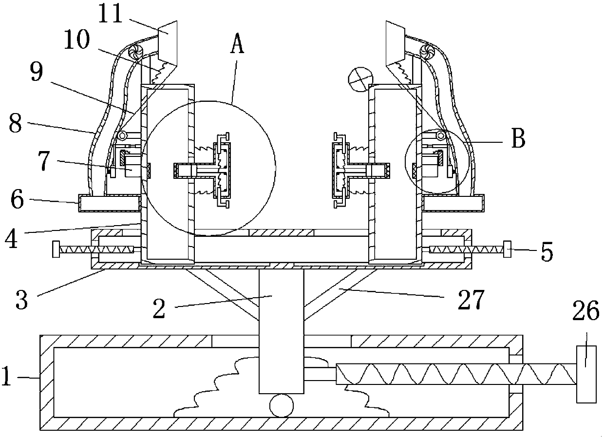
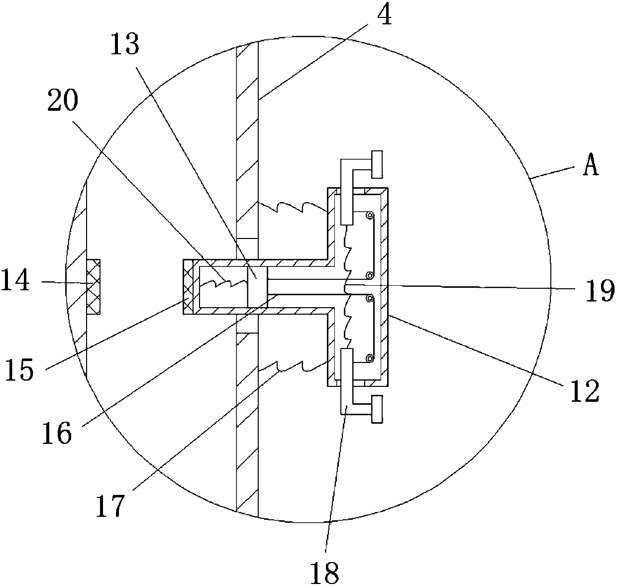
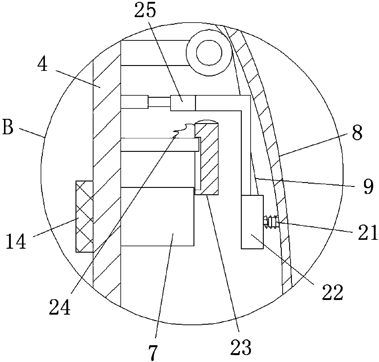
[0018] see Figure 1-3 , the present invention provides a technical solution:

[0019] A machining fixture, comprising a workbench 1, the workbench 1 is a hollow structure, the inner bottom wall of the workbench 1 is hinged with one end of a rotating rod 2, and the side wall of the rotating rod 2 is connected to the inner wall of the workbench 1 through a seventh spring. The bottom wall is connected, and the other end of the rotating rod 2 slides through the ...


PUM


Abstract

The invention discloses a machining fixture, including a worktable. The machining fixture has a simple structure. By rotating two first threaded rods in opposite directions, the workpiece is clamped by two T-shaped pressing boxes. At the same time, the first conductive The sheet is in contact with the second conductive sheet, the electromagnet is energized to magnetically attract the first iron block and the second iron block, and the two L-shaped rods located on the same horizontal plane are moved toward each other through the second pulling rope, and the workpiece is further clamped by the pressing block. The scrap iron scraps generated are sucked into the collection box by the fan. When the scrap iron scraps on the surface of the electromagnet become more and more, the attraction force of the second iron block by the electromagnet becomes smaller. Under the action of the fifth spring, The two second iron blocks move against each other, the first magnet and the second magnet repel, and the scraper moves downward to push the iron scraps on the electromagnet into the collection box. Under the action of the first spring, the suction nozzle generates Deflection to increase the range of scrap iron filings.

Description

technical field [0001] The invention relates to the technical field of machining fixtures, in particular to a machining fixture. Background technique [0002] When drilling a mechanical workpiece, it is generally necessary to clamp the workpiece through a fixture for reprocessing, but the fastening force of the fixture in the prior art is not ideal, and the function of the fixture is single, and it does not have the function of processing scrap iron chips. For this reason, a machining fixture is proposed. Contents of the invention [0003] The object of the present invention is to provide a machining fixture to solve the problems raised in the background art above. [0004] In order to achieve the above object, the present invention provides the following technical solutions: a mechanical processing fixture, including a workbench, the workbench is a hollow structure, one end of a rotating rod is hinged to the inner bottom wall of the workbench, and the side of the rotatin...

Claims


Application Information

Patent Timeline
IPC IPC(8): B23Q3/06B23Q11/00
CPCB23Q3/06B23Q11/0046
Inventor 吴哲明李华想杨海龙
Owner 吴哲明
Learn More