Oil-sludge separation discharging device

A discharge device and oil sludge separation technology, applied in the petroleum industry, hydrocarbon oil treatment, pyrolysis treatment of sludge, etc., can solve problems such as deflagration accidents, achieve the effect of preventing deflagration accidents and compact volume

Pending Publication Date: 2018-04-13
长春三真实业有限公司
View PDF7 Cites 0 Cited by
  • Summary
  • Abstract
  • Description
  • Claims
  • Application Information

AI Technical Summary

Problems solved by technology

Since the slag outlet is connected to the interior of the rotary kiln, air can easily enter the interior of the rotary kiln from the slag outlet during slag discharge, causing deflagration accidents

Method used


Image

  • Oil-sludge separation discharging device

Examples


Embodiment Construction

[0024] The present invention will be described in detail below in conjunction with the accompanying drawings.

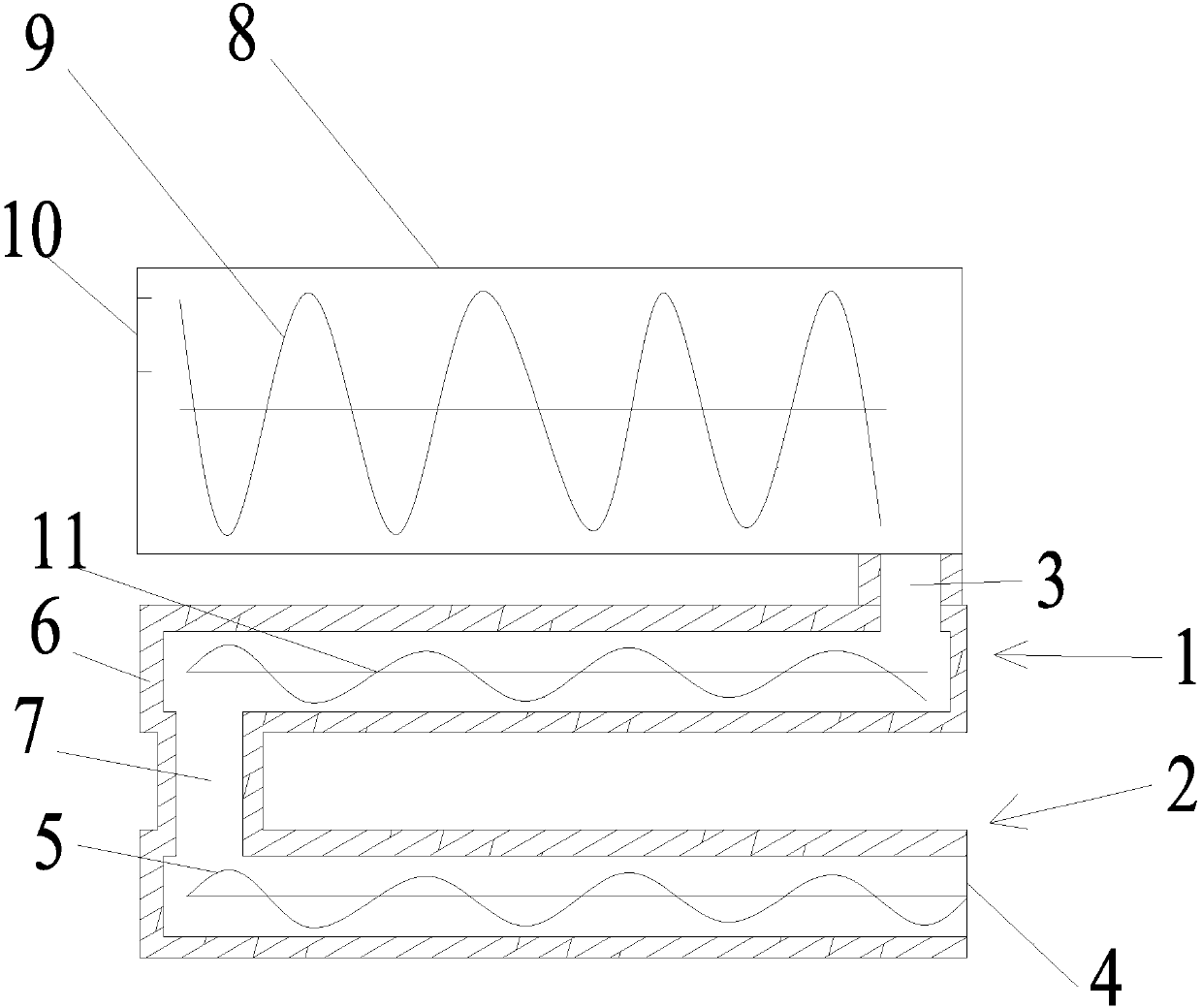
[0025] Such as figure 1 As shown, an oil sludge separation and discharging device of the present invention is arranged at the slag outlet 3 of the rotary kiln 8 of the oil sludge separation device. The rotary kiln 8 is provided with a third screw conveyor 9, which is used to transport the raw oil sludge to be processed from the feed port 10 to the slag outlet 3. During the above transportation process, the original oil sludge is decomposed by high temperature. The temperature of the slag discharged from the slag outlet 3 is generally about 600°C.

[0026] The oil sludge separating and discharging device of the present invention comprises a first conveying pipeline 1 and a second conveying pipeline 2 arranged in parallel up and down. Wherein, one end of the first conveying pipe 1 is connected with the slag outlet 3, and the other end is connected with a connecting p...


PUM

PropertyMeasurementUnit
lengthaaaaaaaaaa
diameteraaaaaaaaaa
lengthaaaaaaaaaa

Abstract

The invention relates to an oil-sludge separation discharging device, comprising a first conveying pipeline and a second conveying pipeline, wherein the first conveying pipeline is arranged at a slaghole of a rotary kiln, one end of the first conveying pipeline is connected with the slag hole, and the other end of the first conveying pipeline is connected with a connecting pipeline; the second conveying pipeline is arranged under the first conveying pipeline, one end of the second conveying pipeline is connected with the connecting pipeline, and a discharge hole is formed at the other end ofthe second conveying pipeline; water jackets are respectively arranged at the outer layers of the first conveying pipeline and the second conveying pipeline; the first conveying pipeline is internallyprovided with a first screw conveyer, and the first screw conveyer can be used for conveying dregs falling from the slag hole to the connecting pipeline so as to enable the dregs to fall into the second conveying pipeline; the second conveying pipeline is internally provided with a second screw conveyer, and the second screw conveyer can be used for conveying the dregs falling from the connectingpipeline to the discharge hole so as to discharge the dregs outside. The oil-sludge separation discharging device is arranged at the slag hole of the rotary kiln of an oil-sludge separation device; due to the arrangement of the two stages of conveying pipelines, the air backflow is well limited, and the deflagration accidents are further effectively prevented.

Description

technical field [0001] The invention relates to a discharge device, in particular to an oil sludge separation and discharge device. Background technique [0002] Oily sludge is soil mixed with oil. Oilfields will produce a certain amount of oily sludge in the process of oil and gas production, mainly from two aspects: one is that crude oil is carried from the formation to the ground and deposited in various containers, large tanks and recovery pools and other ground facilities, which need to be cleaned regularly The second is the sludge generated from oil well operations, perforation of oil collection and transportation pipelines, and oil theft. [0003] The physical and chemical properties of oilfield oily sludge are very complex, generally containing a large amount of aged crude oil, wax, asphaltene, colloids and suspended solids, bacteria, parasites, salts, acid gases, corrosion products and a small amount of mechanical impurities, copper, Heavy metal salts such as zinc...

Claims


Application Information

Patent Timeline
Patent Type & Authority Applications(China)
IPC IPC(8): C02F11/10C10G1/00C02F103/10
CPCC10G1/00C02F11/10C02F2103/10C10G2300/1003
Inventor 苏忠
Owner 长春三真实业有限公司
Why Eureka
Try Eureka