
Super high-level mixed type space steel gridding cartridge tube-in-tube structure and manufacturing method

A technology of grid structure and steel grid, which is applied in special structures, building components, building structures, etc., to achieve the effect of reducing the cost, increasing the number of grids, and reducing the thickness of the floor structure

Inactive Publication Date: 2018-04-13
湖南金海集团有限公司
View PDF5 Cites 0 Cited by
  • Summary
  • Abstract
  • Description
  • Claims
  • Application Information

AI Technical Summary

Problems solved by technology

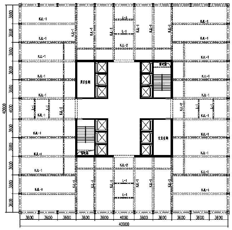
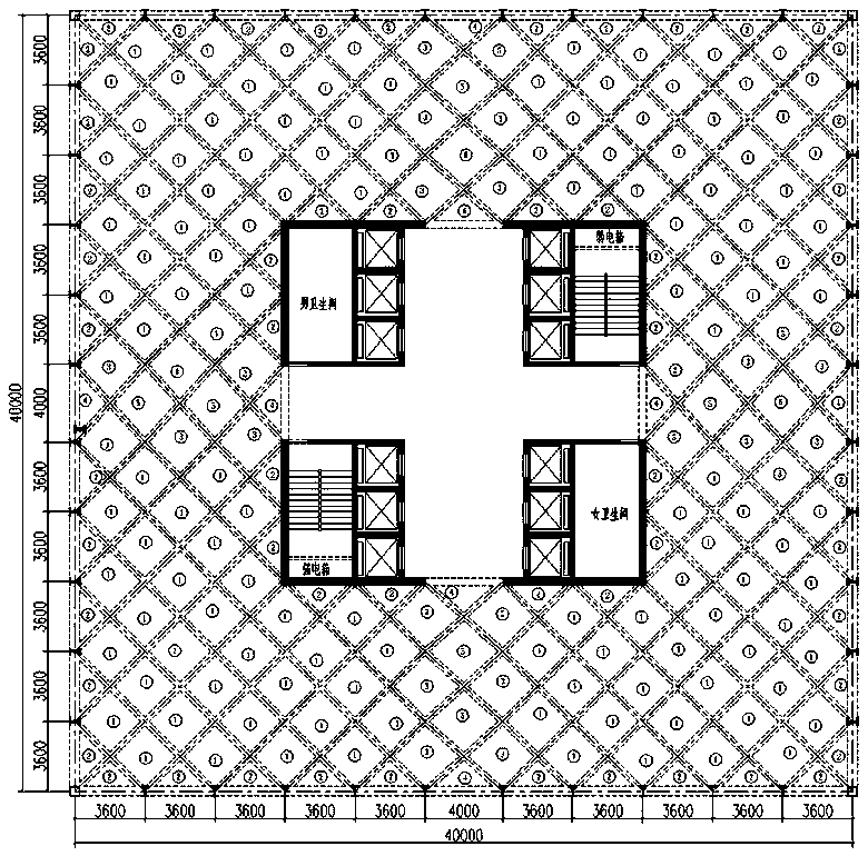
When the building function and shape require individual column nets to be enlarged or reduced, for example, when the surrounding central column nets are increased from 3.6m to 4m, the original steel grid box-type tube-in-tube hybrid structure with orthogonal inclined spaces will not be able to meet the actual construction requirements. need

Method used


Image

  • Super high-level mixed type space steel gridding cartridge tube-in-tube structure and manufacturing method
  • Super high-level mixed type space steel gridding cartridge tube-in-tube structure and manufacturing method
  • Super high-level mixed type space steel gridding cartridge tube-in-tube structure and manufacturing method

Examples


Embodiment Construction

[0040] In order to make the object, technical solution and advantages of the present invention clearer, the present invention will be further described in detail below in conjunction with the examples.

[0041] The application principle of the present invention will be further described below in conjunction with the accompanying drawings and specific embodiments.

[0042] The super high-rise mixed space steel grid box-type tube-in-tube structure includes a steel grid frame distributed on four sides around the periphery, a concrete core tube, and a steel grid hollow floor; The grid frame is connected to form a box structure; the box structure is rigidly connected with the concrete core tube through the wall frame unit to form a box-type tube-in-tube structure; the concrete core tube is cast on site; the steel grid hollow floor is made of Several steel vierendeel beams are rigidly connected with surrounding column nets to form a grid unit; the central column net on four sides of...


PUM


Abstract

The invention discloses a super high-level mixed type space steel gridding cartridge tube-in-tube structure. The super high-level mixed type space steel gridding cartridge tube-in-tube structure includes a steel gridding frame with quadrangular distribution on the periphery, a concrete core tube, and a steel gridding hollow floor system. The steel gridding hollow floor system is connected with thesteel gridding frame to form a cartridge structure through a wall shelf unit. The cartridge structure forms into a cartridge tube-in-tube structure through rigid connection of the wall shelf unit andthe concrete core tube. The concrete core tube is poured in site. The steel gridding hollow floor system is composed of gridding units formed by two-and-two rigid connection of multiple steel hollowbeams and surrounding column grids. The central column grids of the four sides of the steel gridding hollow floor system are larger than the other column grids. The steel gridding frame is composed ofconnection of rectangular frame units. Each frame unit is formed by welding of a steel column and a cross beam. By using the fabricated mixed type space steel gridding cartridge tube-in-tube structure, when the building function and the modeling need increasing or decreasing of individual column grids, three gridding shapes are added, so that the number of steel grids in the overall floor systemis increased. Thickness of the floor system structure is decreased; in the same building height, the building area is increased, so that the overall project cost is reduced, and the economic benefitsare increased.

Description

technical field [0001] The invention belongs to the technical field of steel structures, and in particular relates to a super-high-rise hybrid space steel grid box-type tube-in-tube structure and a manufacturing method. Background technique [0002] For a long time, in addition to the reinforced concrete structure system, super high-rise (H>100m) office buildings have generally adopted a steel frame and a concrete core tube to form a steel frame, a tube hybrid structure, and a tube structure composed of a steel dense column outer tube and a concrete core tube. cartridge mixing structure ( figure 1 ), these traditional structural systems are not capable of flexible division of large bays and comprehensive application of rooms in terms of building functions, and must follow the requirement of "where there are walls, there must be beams", such as figure 1 The super high-rise office building shown in the figure adopts the traditional 3.6m steel outer cylinder column grid and...

Claims

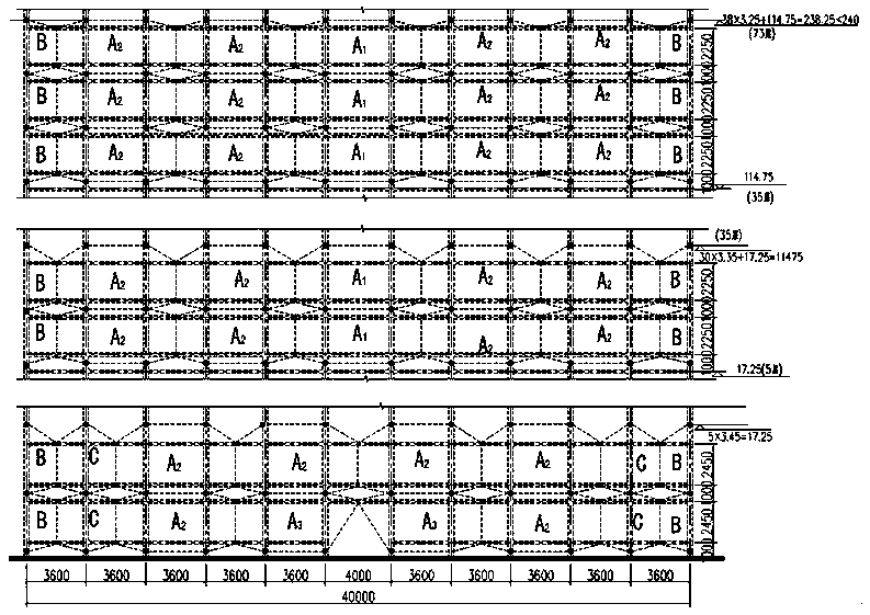

Application Information

Patent Timeline
Patent Type & Authority Applications(China)
IPC IPC(8): E04B1/348E04B1/34E04B1/19E04B1/24E04B1/58
CPCE04B1/34807E04B1/19E04B1/24E04B1/2403E04B1/34
Inventor 马克俭曾勇马范军黄瑞五朱宏伟
Owner 湖南金海集团有限公司
Learn More