Water wave projection lamp

A projection lamp and water pattern technology, applied in the field of stage effect lamps, can solve the problems of reducing the imaging effect, large astigmatism range, large contrast, etc., and achieve the effect of uniform clarity, uniform transmission spot, and high light efficiency.

Pending Publication Date: 2018-04-13
GUANGZHOU DASEN LIGHTING ELECTRONICS
View PDF0 Cites 3 Cited by
  • Summary
  • Abstract
  • Description
  • Claims
  • Application Information

AI Technical Summary

Problems solved by technology

[0002] The existing stage entertainment effect lamps and water pattern LED lights use the principle of optical projection, and use high-power and high-brightness LEDs to illuminate two pieces of water pattern glass with uneven surfaces that alternately rotate to project images, so as to realize the tumbling of water waves and the flow of water droplets. Or the realistic effect of ripples, but most of the lamps on the market currently irradiate the water ripple glass after focusing, and the range of astigmatism will be too large, resulting in a large contrast between the center and the edge of the image clarity of the water ripple projection. The image in the middle is better, but the edges are tailed, which seriously reduces the imaging effect

Method used


Image

  • Water wave projection lamp
  • Water wave projection lamp

Examples


Embodiment 1

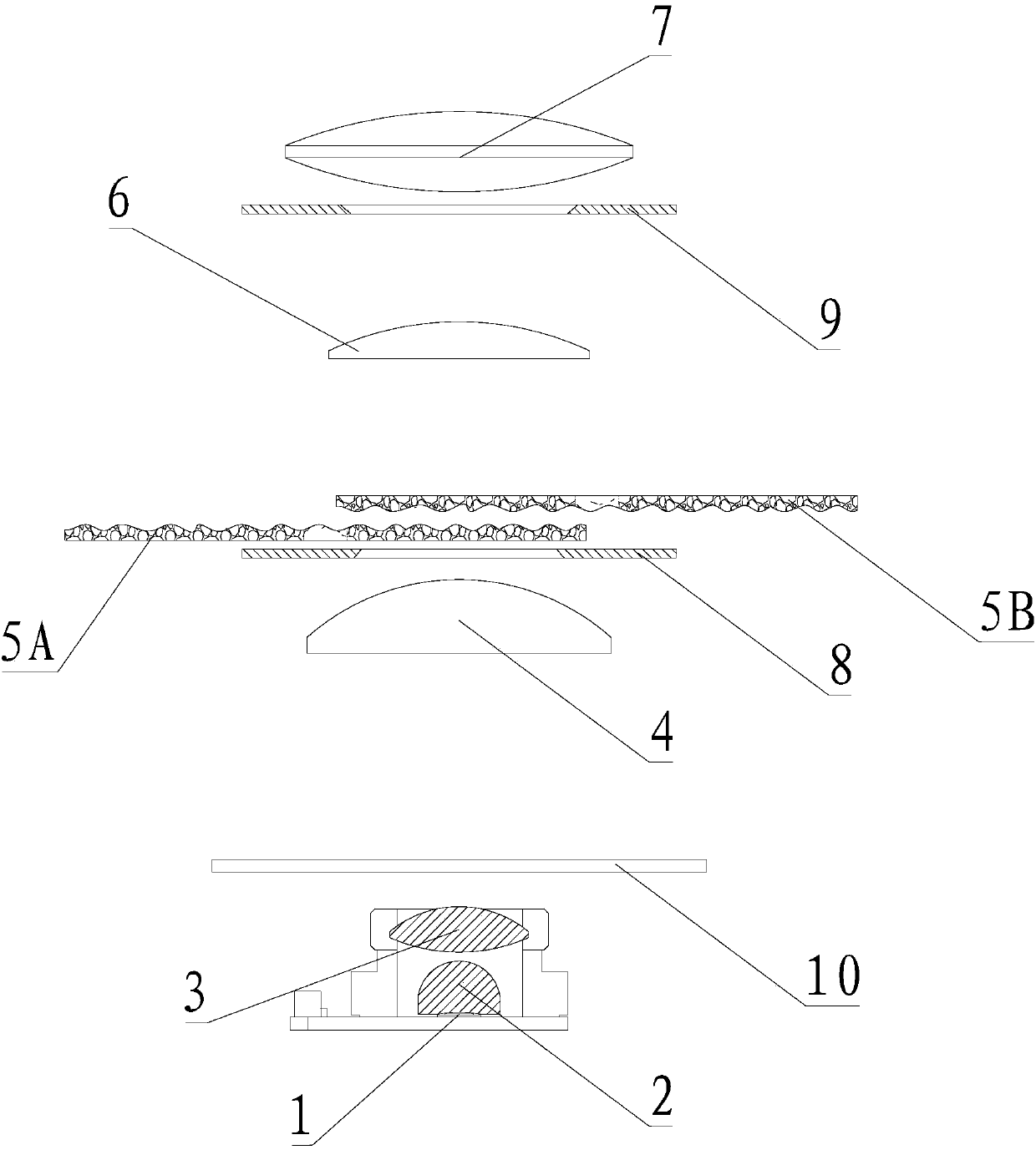
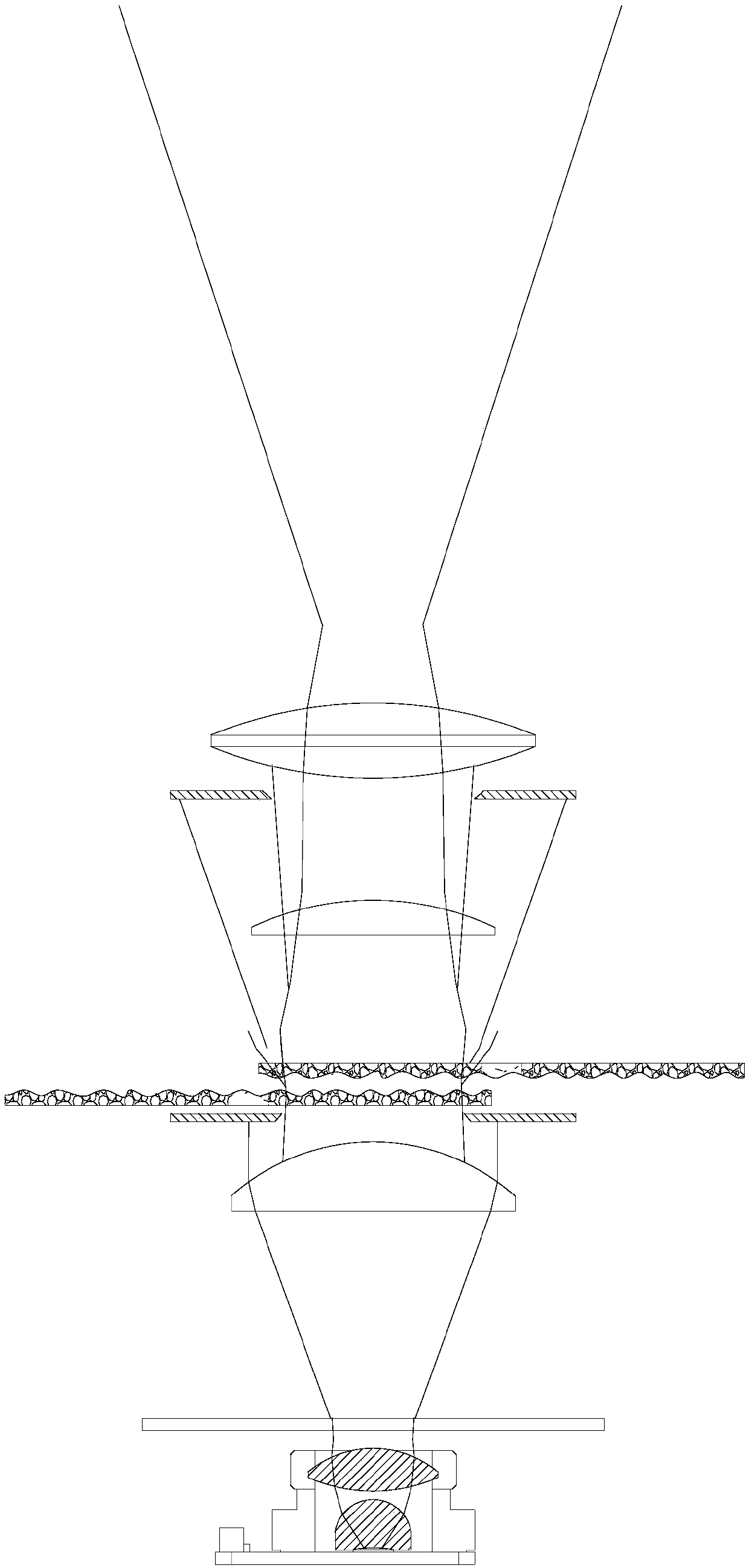
[0021] see figure 1 as well as figure 2 , a watermark projection lamp, comprising a light source, a condenser lens group, a watermark effect component, a focusing lens and an imaging lens arranged in sequence along the outgoing direction of the light, the condenser lens group, the focusing lens and the imaging lens The optical axes are coincident, the focusing lens can reciprocate along the direction of the optical axis, a first light-shielding plate is set between the condenser lens group and the water effect component, and a patterned light-shielding plate is arranged in the middle of the first light-shielding plate hole, and a second light-shielding plate is provided between the focusing lens and the imaging lens, and the second light-shielding plate is provided with a light-through hole.

[0022] In this embodiment, the light source is preferably monochromatic white LED or polychromatic LED, which is collected by a condenser lens group to form a collimated beam, then pas...

Embodiment 2

[0025] On the basis of embodiment 1, the condensing lens group includes a first lens, a second lens and a third lens, the incident light side optical surface of the first lens is a concave surface, and the outgoing light side optical surface is a convex surface; The incident light side optical surface of the second lens is convex, and the light exit side optical surface is convex; the incident light side optical surface of the third lens is plane, and the light exit side optical surface is convex.

[0026] In this embodiment, after the light emitted by the light source passes through the first lens, the second lens and the third lens of the condenser lens group, it can form a collimated light beam with a divergence angle less than 10 degrees, so that the light emitted by the light source can be fully utilized. To increase the uniformity of illumination, the collimated beam can also minimize stray light when passing through the uneven surface of the water effect component, and i...

Embodiment 3

[0028] On the basis of Embodiment 2, the water pattern effect component includes first water pattern glass and second water pattern glass arranged in a staggered manner, the first water pattern glass is arranged on one side of the optical path, and the second water pattern glass The glass is arranged on the other side of the optical path, and the two pieces of water wave glass can rotate along their respective rotation axes, and the rotation axes are parallel to the optical axis.

[0029] In this embodiment, the first water pattern glass can be driven by the motor to rotate the first rotating shaft, and the second water pattern glass can be driven by the motor to rotate the second rotating shaft, wherein the first rotating shaft and the second rotating shaft are respectively arranged on both sides of the optical path, and the first rotating shaft and the second rotation axis are parallel to the optical axis, and the light path passes through the overlapping area of ​​the two pi...


PUM

PropertyMeasurementUnit
Diameteraaaaaaaaaa

Abstract

The invention provides a water wave projection lamp comprising a light source, a condensing lens group, a water wave effect component, a focusing lens and an imaging lens which are arranged in sequence in the light emitting direction. The optical axes of the condensing lens group, the focusing lens and the imaging lens coincide, and the focusing lens can reciprocate in the optical axis direction;a first light screen is arranged between the condensing lens group and the water wave effect component, and the middle of the first light screen is provided with a pattern light-pass hole; a second light screen is arranged between the focusing lens and the imaging lens, and provided with a light-pass hole. The water wave projection lamp provided by the invention has the beneficial effects that theprovided water wave projection lamp can be used for collection of light rays and shielding of stray light rays, and the light rays of the projection lamp have the features of high lighting effect anduniform transmission light spots after being collected for many times; since the stray light rays are shielded effectively, the definitions of the light spot center and edges of the water wave projection lamp are consistent, and the problem of serious fluctuation tailing of the light spot edges is solved.

Description

technical field [0001] The invention relates to the field of stage effect lamps, in particular to a water pattern projection lamp. Background technique [0002] The existing stage entertainment effect lamps and water pattern LED lights use the principle of optical projection, and use high-power and high-brightness LEDs to illuminate two pieces of water pattern glass with uneven surfaces that alternately rotate to project images, so as to realize the tumbling of water waves and the flow of water droplets. Or the realistic effect of ripples, but most of the lamps on the market currently irradiate the water ripple glass after focusing, and the range of astigmatism will be too large, resulting in a large contrast between the center and the edge of the image clarity of the water ripple projection. The image in the middle is better, but the edges are tailed, which seriously reduces the imaging effect. Contents of the invention [0003] The technical problem to be solved by the ...

Claims


Application Information

Patent Timeline
IPC IPC(8): F21S10/00F21S10/02F21V14/00F21V14/06F21V13/00F21W131/105F21W131/406F21Y115/10F21Y113/13
CPCF21S10/00F21S10/02F21V13/00F21V14/00F21V14/06F21Y2115/10F21Y2113/13F21W2131/406F21W2131/105
Inventor 许法卿薛金山
Owner GUANGZHOU DASEN LIGHTING ELECTRONICS
Why Eureka
Try Eureka