Heat storage plate type heat exchanger

A heat storage plate and heat exchanger technology, applied in the direction of heat exchanger type, indirect heat exchanger, heat storage equipment, etc., can solve the problem of not having the ability to adjust heat load, and achieve the goal of being beneficial to heat exchange and having heat storage. ability, the effect of improving thermal conductivity

Inactive Publication Date: 2018-04-13
NORTH CHINA ELECTRIC POWER UNIV (BAODING) +1
View PDF4 Cites 7 Cited by
  • Summary
  • Abstract
  • Description
  • Claims
  • Application Information

AI Technical Summary

Problems solved by technology

[0003] The plate heat exchangers commonly used in local heat exchange stations do not have the ability to adjust heat loads.

Method used


Image

  • Heat storage plate type heat exchanger
  • Heat storage plate type heat exchanger
  • Heat storage plate type heat exchanger

Examples


Embodiment Construction

[0026]The present invention will be further described below in conjunction with the accompanying drawings and embodiments.

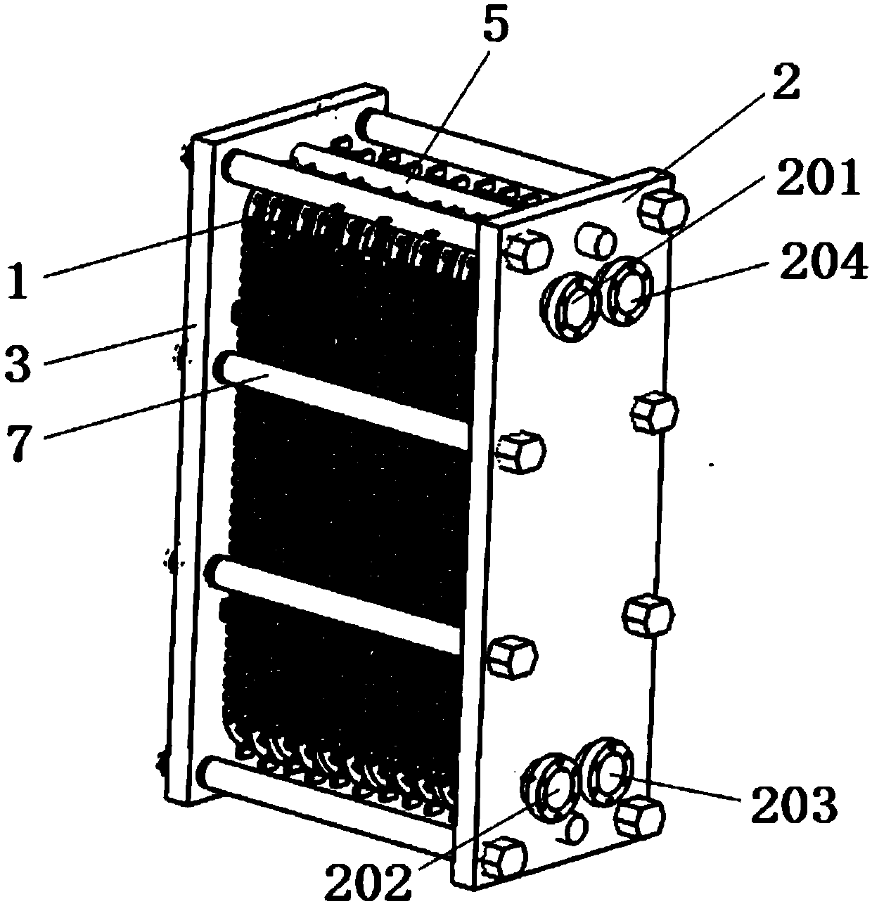
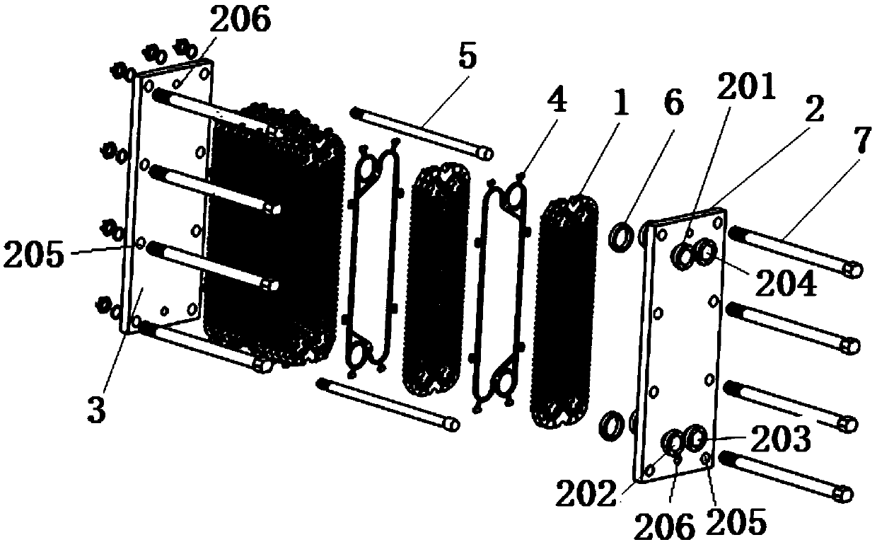
[0027] This embodiment is a heat storage plate heat exchanger, such as figure 1 Schematic diagram of the regenerative plate heat exchanger and figure 2 The decomposition diagram of the heat storage plate heat exchanger parts, the heat storage plate heat exchanger includes the heat storage heat exchange plate 1, the fixed compression plate 2, the movable compression plate 3, the gasket 4, the guide rod 5, the sealing ring 6 and Compression screw 7. 15 regenerative heat exchange plates 1 are positioned with guide rods 5 and arranged closely between the fixed compression plate 2 and the movable compression plate 3, and the two ends of a guide rod 5 respectively pass through the fixed compression The guide rod hole 206 on the upper end of the plate 2 and the movable compression plate 3, the two ends of the other guide rod 5 pass through the guide rod hole ...


PUM


Abstract

The invention belongs to the technical field of combined heat and power generation for heating and relates to a heat storage plate type heat exchanger. 13-20 heat storage type heat exchange plates arelocated and closely arranged between a fixed compression plate and a movable compression plate through guide rods. Each sealing pad is arranged between the corresponding two adjacent heat storage type heat exchange plates. Every two adjacent sealing pads are placed in opposite directions. The heat storage type heat exchange plates are tightly pressed through compression threaded rods, so that theheat storage plate type heat exchanger is formed. Each heat storage type heat exchange plate is provided with a plate type cavity, wherein a phase change heat storage material is encapsulated in eachplate type cavity. By means of phase change latent heat of the phase change material, the plate type heat exchanger has the heat storage capability. When a combined heat and power generation unit participates into load peak shaving of an electric network, the phase change heat storage material mainly stores or releases heat in the form of the phase change latent heat, and the heat storage plate type heat exchanger can achieve the effect of heating load adjustment. By means of the heat storage plate type heat exchanger, the load peak shaving capability of the combined heat and power generationunit during the heating period is enhanced; the grid connection space of new energy power generation is expanded; and the heat storage plate type heat exchanger is suitable for participating into thecombined heat and power generation unit for electrical load peak shaving.

Description

technical field [0001] The invention belongs to the technical field of cogeneration heat supply, and in particular relates to a heat storage plate heat exchanger. Background technique [0002] According to my country's electric power development blueprint, by 2020 my country's renewable energy power generation will account for more than 15%. Since cogeneration heating units generally adopt the heat-fixed power operation mode in the heating season, the peak-shaving capability of power load is poor, which limits the grid connection of new energy generation with load fluctuations such as wind energy and solar energy, resulting in serious wind and energy curtailment. Therefore, it is one of the key issues facing the field of combined heat and power to explore effective technical approaches to improve the power load peak-shaving capacity of cogeneration units in the heating season and to leave more space for new energy power generation to be connected to the grid. [0003] The p...

Claims


Application Information

Patent Timeline
Patent Type & Authority Applications(China)
IPC IPC(8): F28D20/02
CPCF28D20/021Y02E60/14
Inventor 杜小泽王宇戈志华杨勇平席新铭
Owner NORTH CHINA ELECTRIC POWER UNIV (BAODING)
Why Eureka
Try Eureka