A Combined Method of Micro-area Adaptive Raman Fluorescence Imaging for Deep Space Exploration

A technology for fluorescence imaging and deep space detection, which is applied in Raman scattering, fluorescence/phosphorescence, measuring devices, etc., can solve the problems of extremely high microscopic optical path, unsatisfactory requirements, complex mineral composition, etc., and achieve Raman signal The effect of high signal-to-noise ratio

Active Publication Date: 2020-04-07
SHANGHAI INST OF TECHNICAL PHYSICS - CHINESE ACAD OF SCI
View PDF4 Cites 0 Cited by
  • Summary
  • Abstract
  • Description
  • Claims
  • Application Information

AI Technical Summary

Problems solved by technology

The analysis of Raman-like substances in deep space exploration has higher requirements than conventional Raman applications. The main challenges and technical difficulties are that due to the complex composition of minerals contained in the test rocks and soils, the particle size of the same minerals is extremely small
Therefore, in the micro-area analysis, the laser focus spot is required to be on the order of 1 micron, so that the minerals can be accurately analyzed in the micro-area, and the requirements for the microscopic optical path are extremely high. The spot is affected by the degradation of the laser mode and the diffraction limit, so the focused spot is often larger than 5 microns, which cannot meet the requirements; the combination of a free optical path, a short-wavelength laser, and a high-magnification, high-NA microscopic objective can theoretically obtain extremely Small focusing spot, but because the focusing depth of field is extremely small, it is necessary to find a suitable self-focusing scheme for micro-area analysis and three-dimensional structure analysis, and to ensure that the focusing spot size of each point is consistent and consistent with the design value. At the same time, if the self-focusing time Long, it will affect the scanning imaging speed

Method used


Image

  • A Combined Method of Micro-area Adaptive Raman Fluorescence Imaging for Deep Space Exploration

Examples


Embodiment Construction

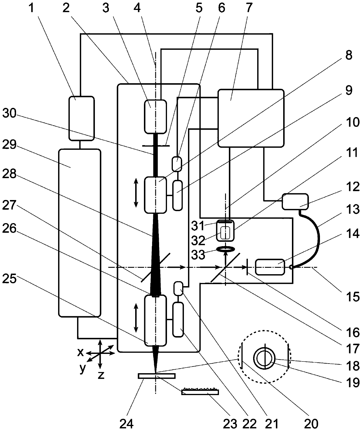
[0035] The specific embodiment of the present invention is as figure 1 shown.

[0036] The adaptive Raman fluorescence imaging combination method proposed by the present invention is realized on an adaptive Raman fluorescence imaging combination system, which consists of a main controller 7, a spectrometer 12, an optical fiber 13, a three-dimensional motor driver 1, and a three-dimensional The precision electric platform 29 is composed of the optical head 2;

[0037] The optical head 2 is composed of an ultraviolet Raman laser 3, an ultraviolet interference filter 5, a secondary motor driver 6, a secondary linear electric platform 9, a low-magnification ultraviolet microscope objective lens 8, a dichroic mirror 27, and a long working distance high-magnification ultraviolet display. Composition of micro objective lens 25, main motor driver 21, main linear electric platform 22, ultraviolet Rayleigh filter 16, proportional beam splitter 17, micro objective lens 14, tube lens 33 ...


PUM


Abstract

The invention discloses a self-adaptive combined Raman fluorescence imaging method for a deep-space exploration micro-area. The method is implemented on a self-adaptive combined Raman fluorescence imaging system, and comprises the following four steps: self-adaptive focusing and calibration of expected focal spots; single-point tight focusing of an exploration object; acquisition of Raman fluorescence and imaging information; and scanning micro-area analysis. The method has the beneficial effects that the diameter of a focused light spot can be self-adaptively adjusted during micro-area analysis; the regional average gray degree of an electronic ocular lens is used as the intensity of a scanning imaging point, and the requirements of both self-focusing and wide-spectrum scanning imaging can be met at the same time; and active laser Raman, hyperspectral fluorescence and visible wide-spectrum scanning image of three-dimensional space can be realized at the same time, and a variety of information is provided for micro-area analysis.

Description

technical field [0001] The invention relates to a substance detection method, in particular to a substance detection method using scanning laser Raman imaging, scanning laser-induced fluorescence imaging and area array wide-spectrum scanning imaging, which is suitable for the detection of substances in the open environment of deep space exploration planets, It belongs to the field of planetary in-situ detection. Background technique [0002] For future deep space exploration, higher requirements are put forward for material composition detection technology and methods, and the in-situ fine detection capability is the highest point of technology aimed at by all aerospace powers. Fine detection requires a smaller laser focus point, a small amount of analyzed substances, more abundant elements and molecular types, more accurate quantification, and it is carried out under the monitoring of extremely high spatial resolution imaging. [0003] Laser Raman (Raman) and ultraviolet l...

Claims


Application Information

Patent Timeline
Patent Type & Authority Patents(China)
IPC IPC(8): G01N21/64G01N21/65
CPCG01N21/64G01N21/6402G01N21/645G01N21/6458G01N21/65G01N2021/6423G01N2021/6471G01N2021/6495G01N2021/655
Inventor 万雄袁汝俊
Owner SHANGHAI INST OF TECHNICAL PHYSICS - CHINESE ACAD OF SCI
Why Eureka
Try Eureka